Module 3 Formstorming
Weekly Activity Template
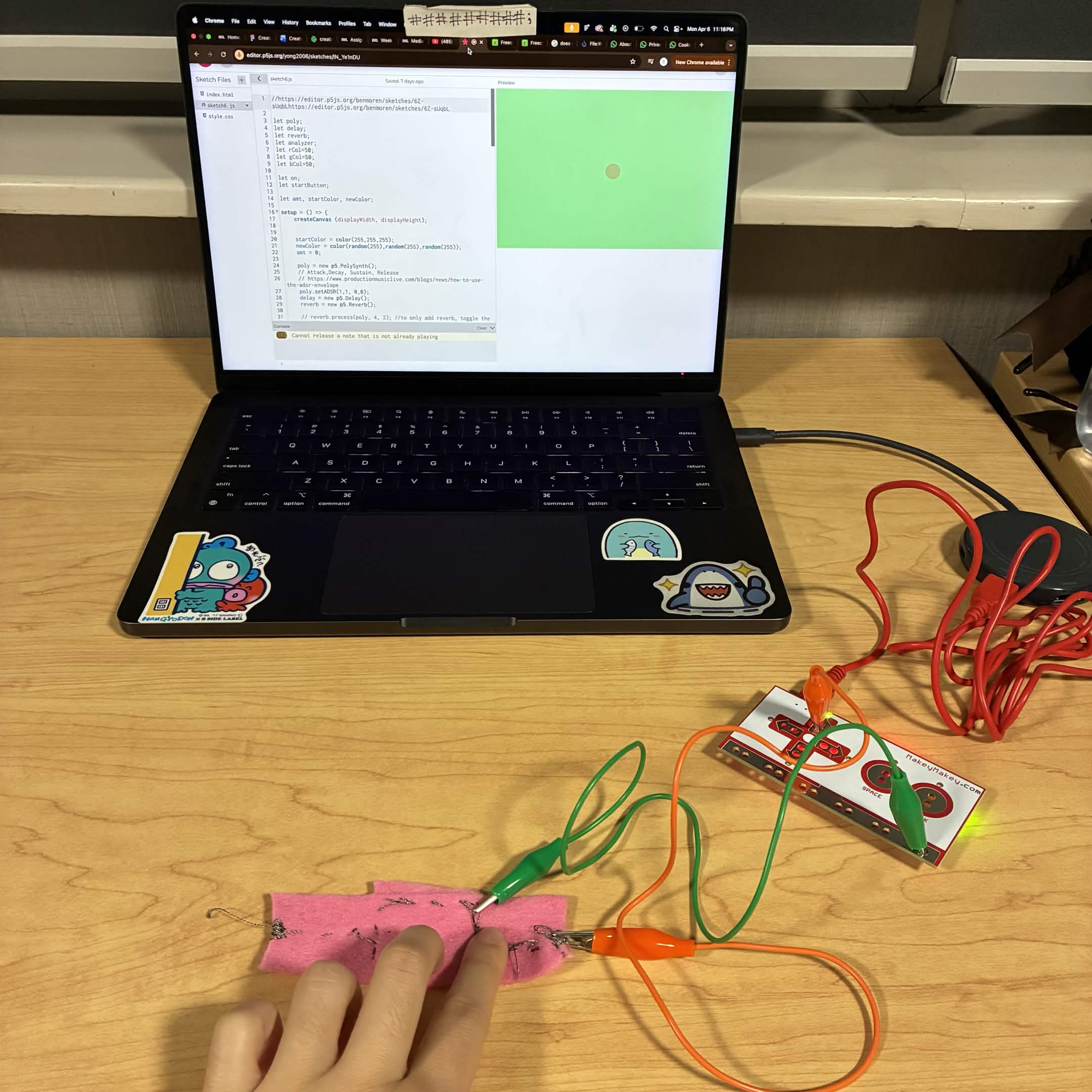
Yvy Ong - My journey connecting physical touch with a P5.js digital visualization to create a unified and integrated design
Project 3
Module 3
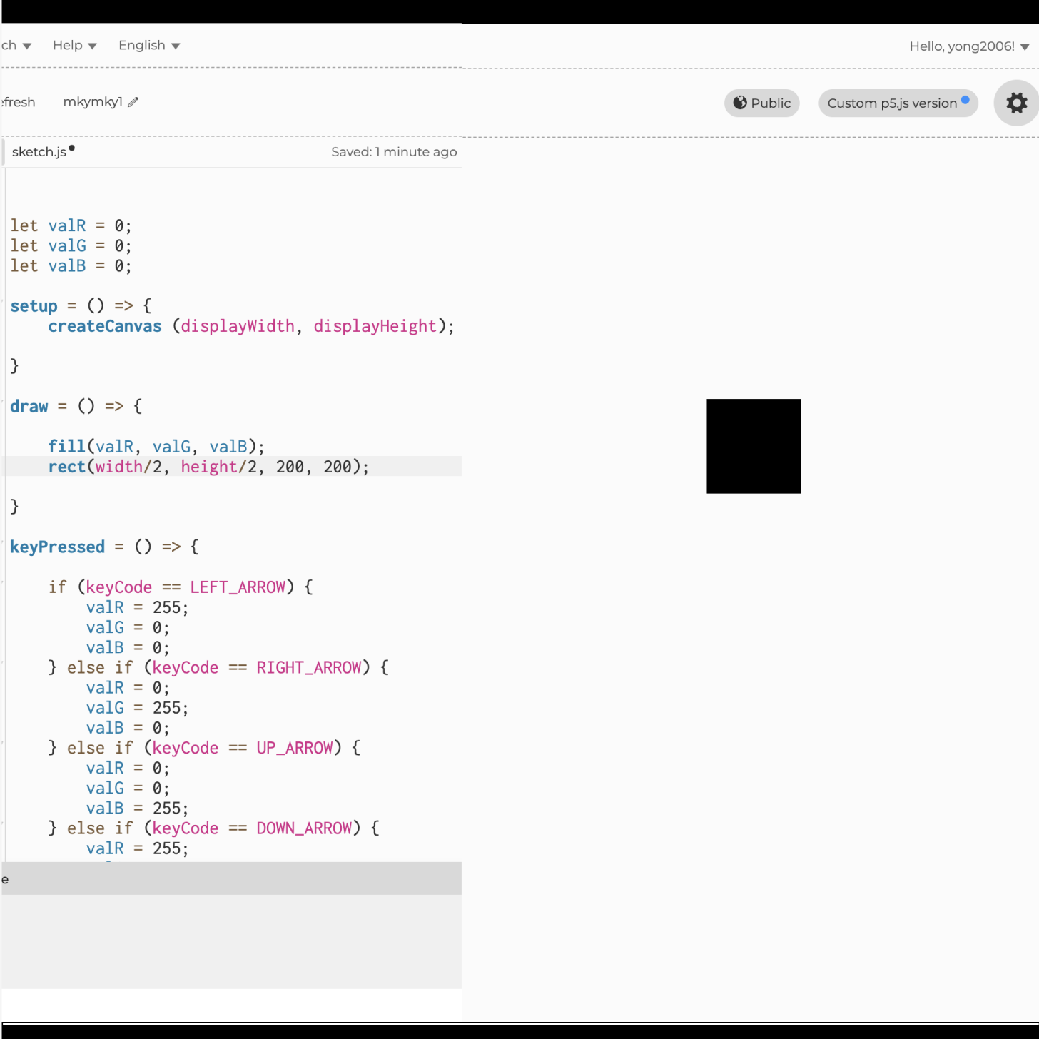
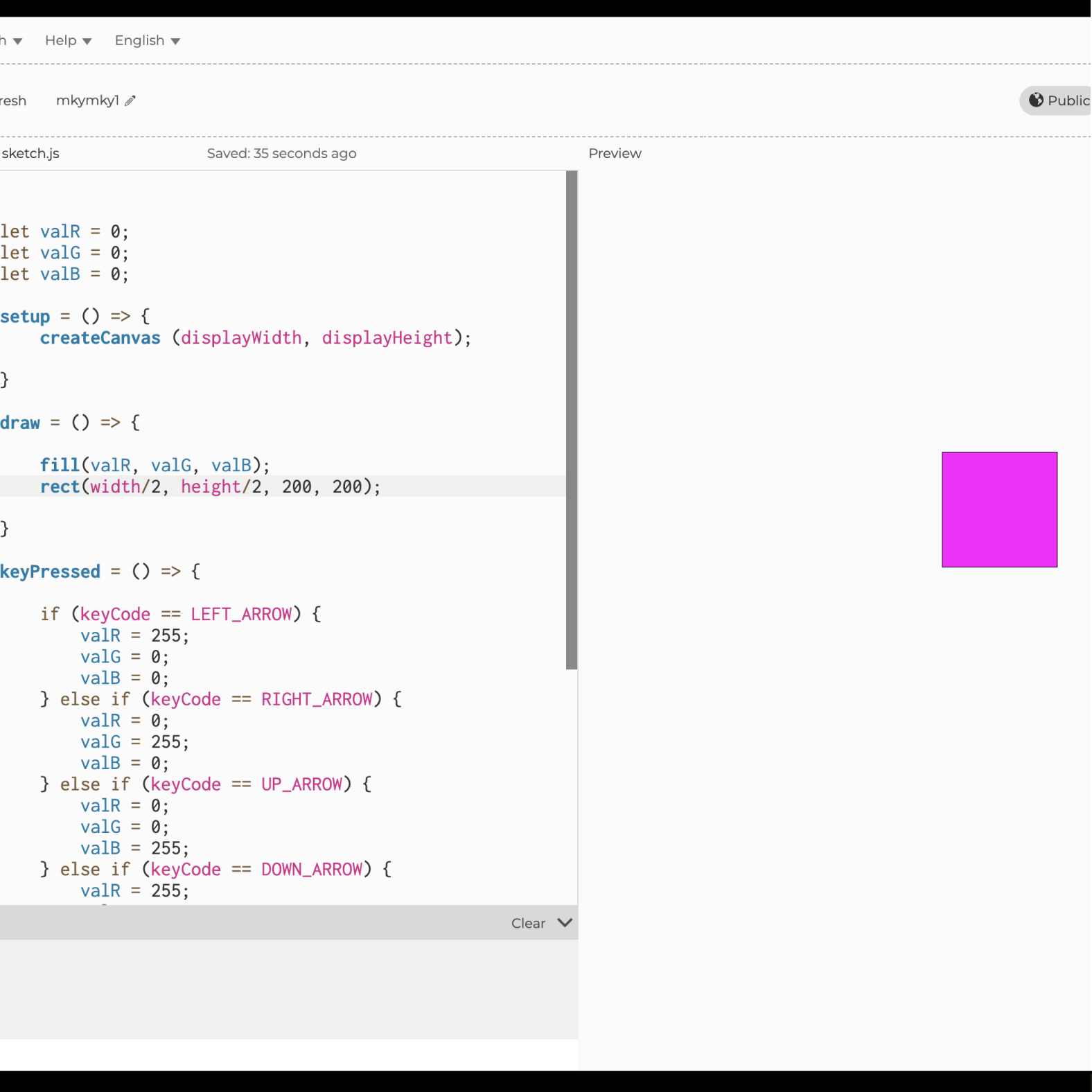
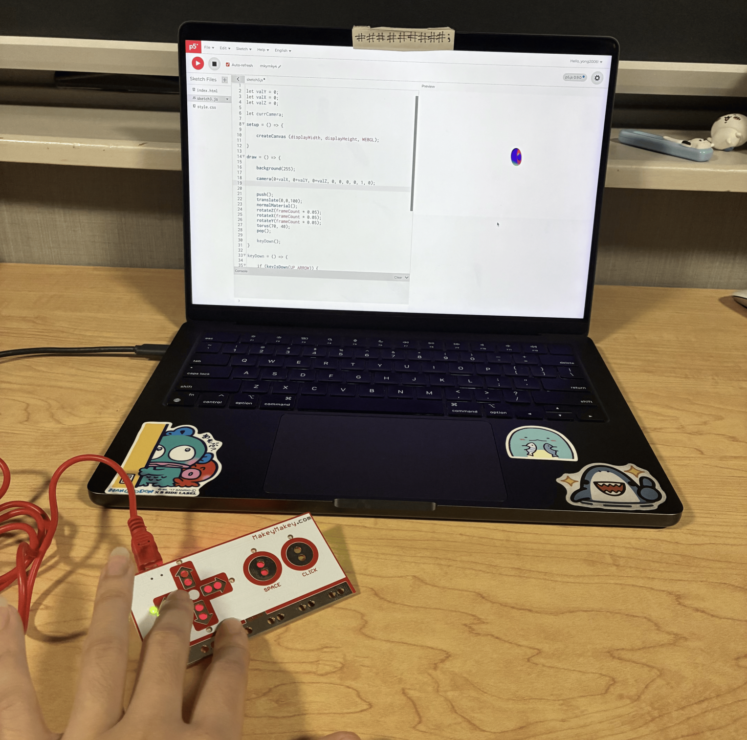
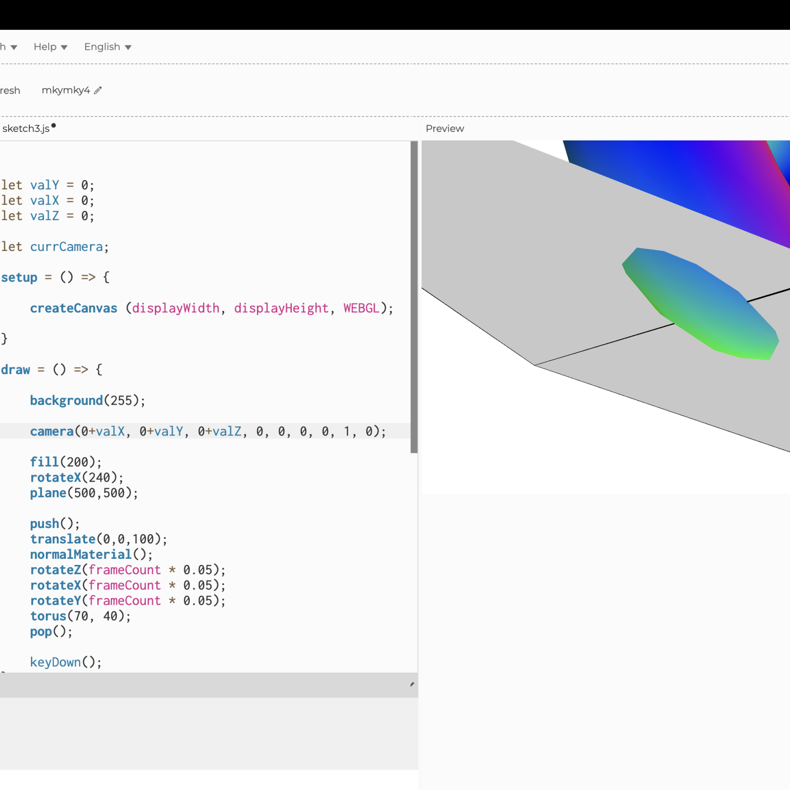
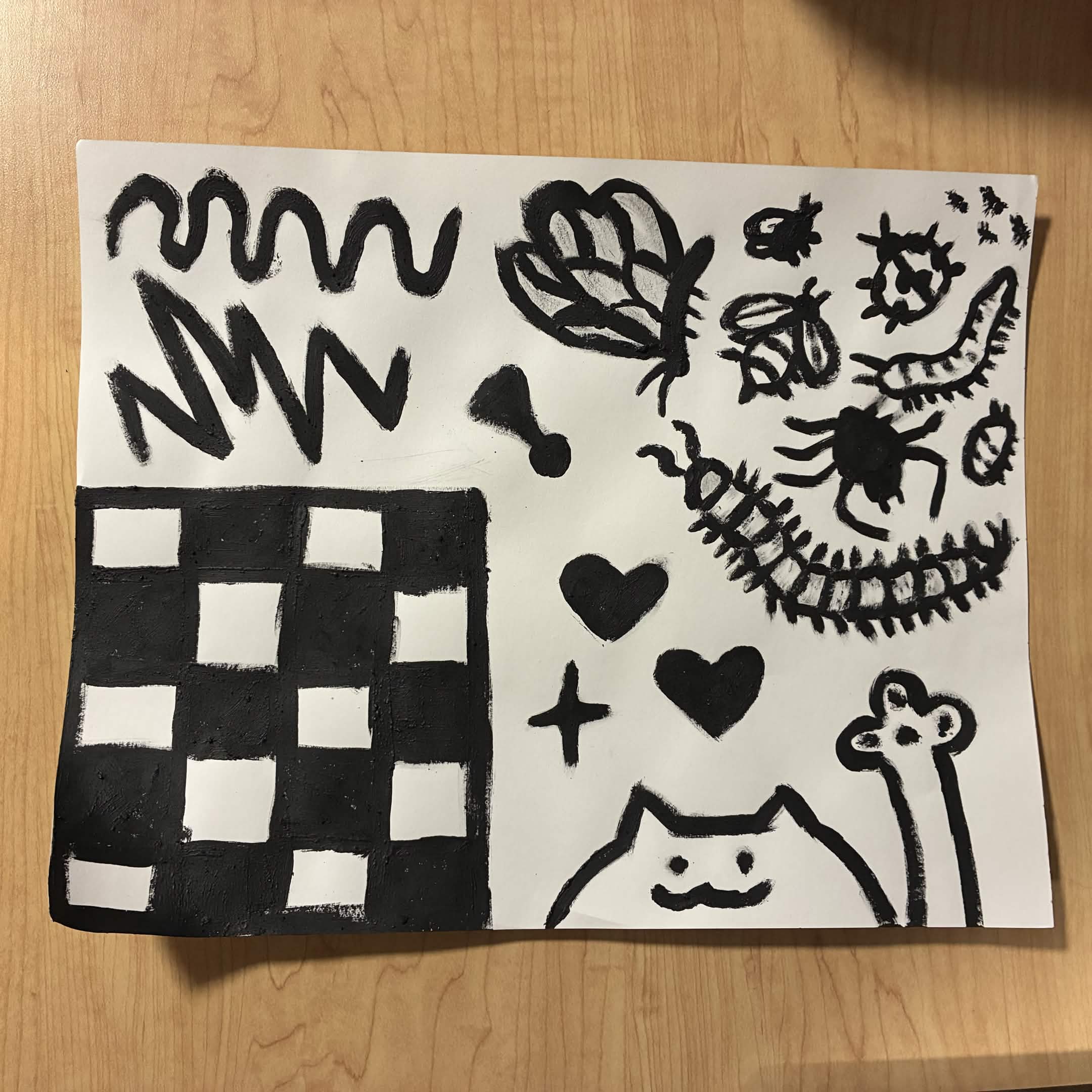
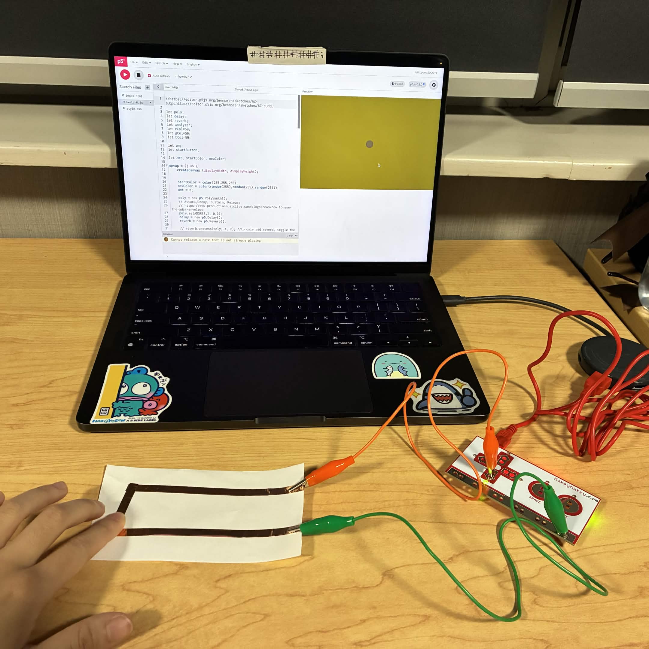
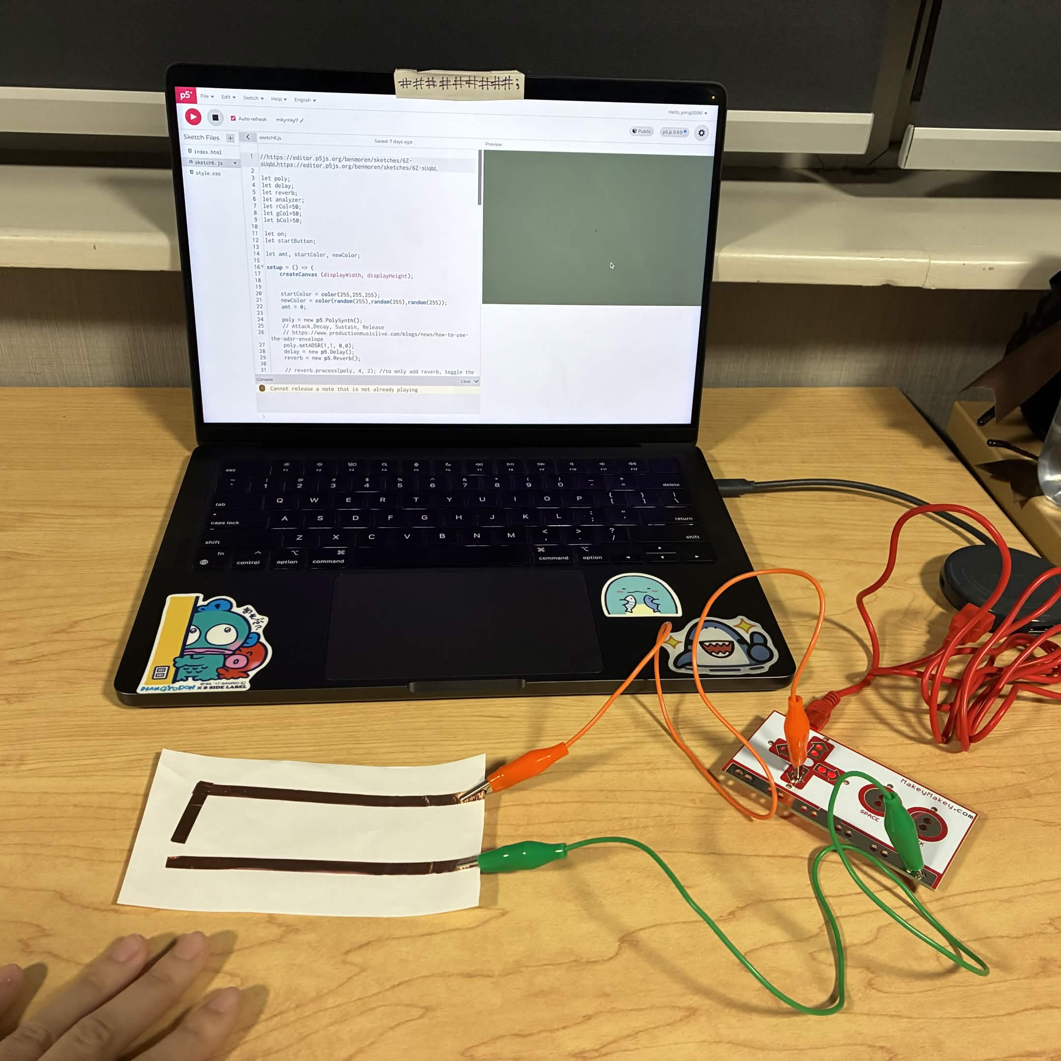
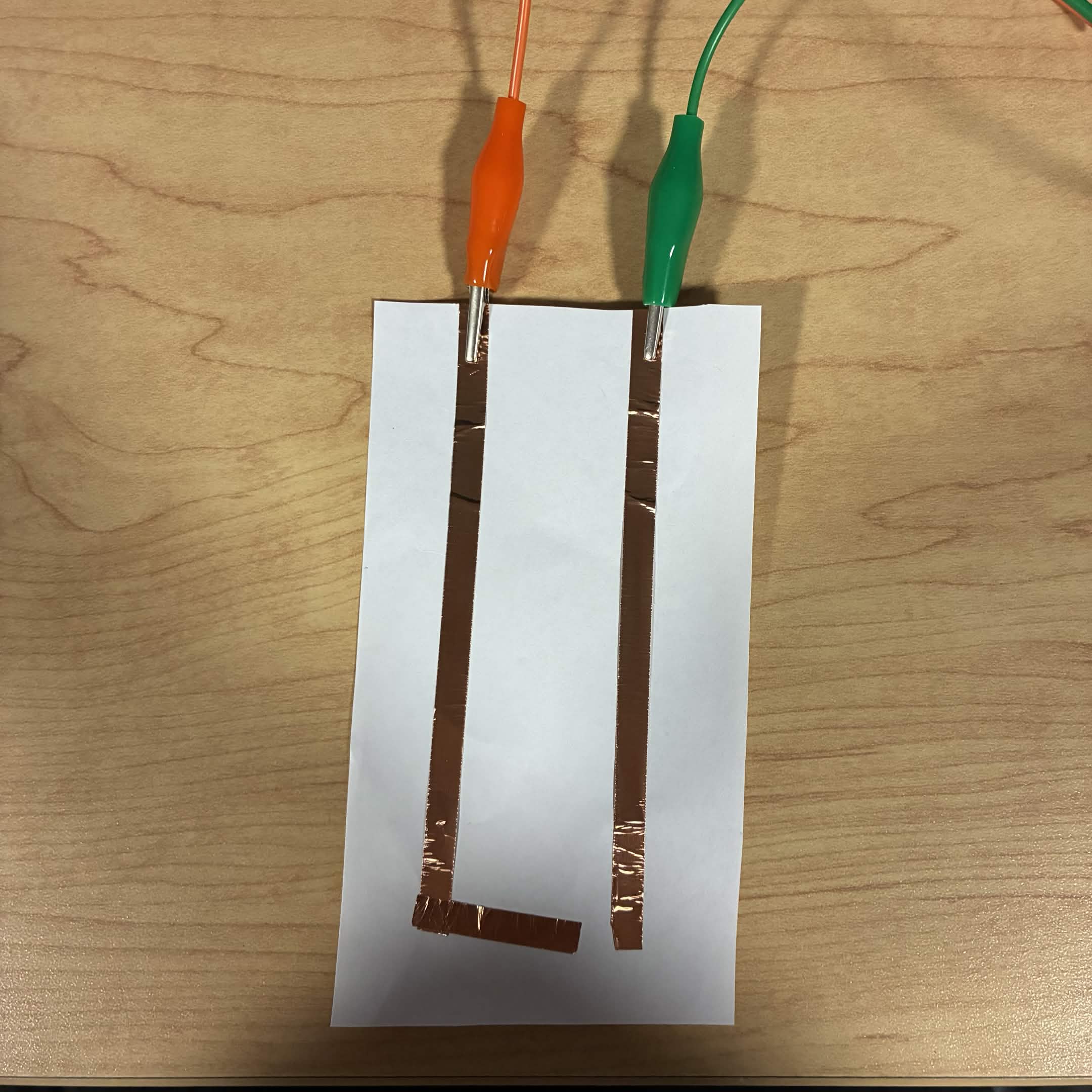
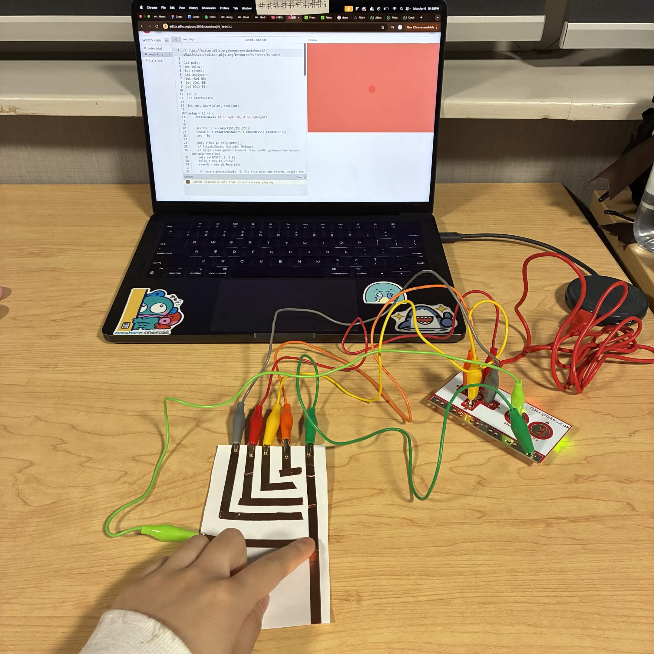
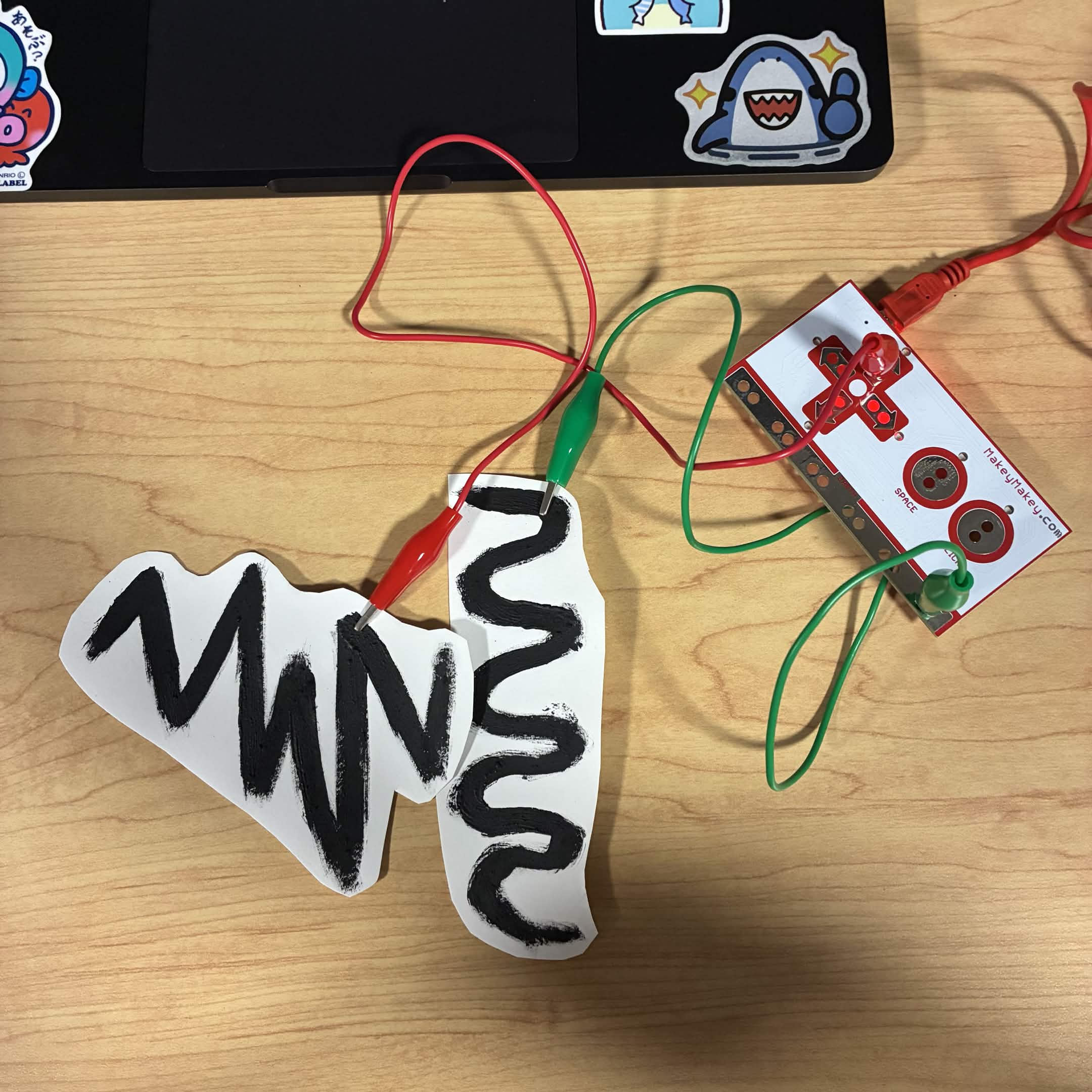
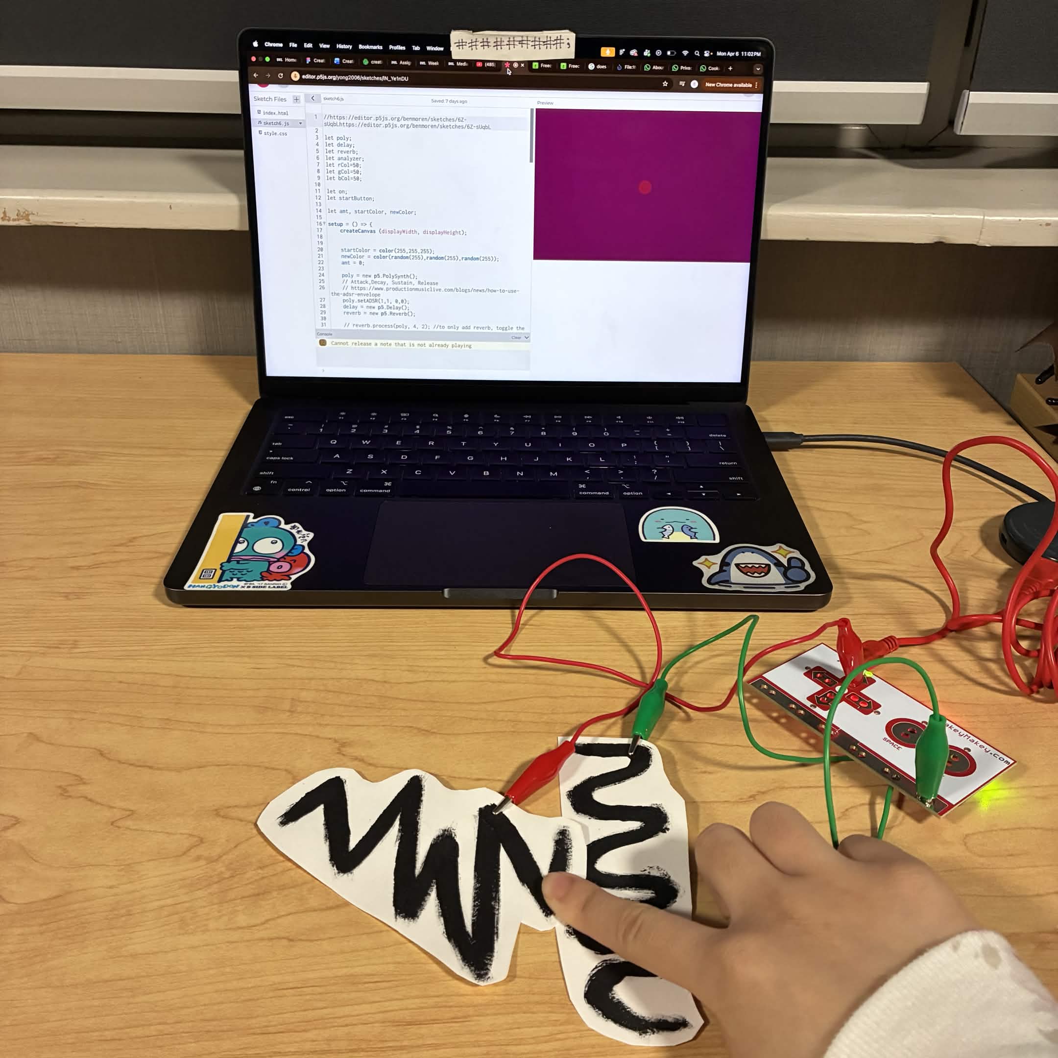
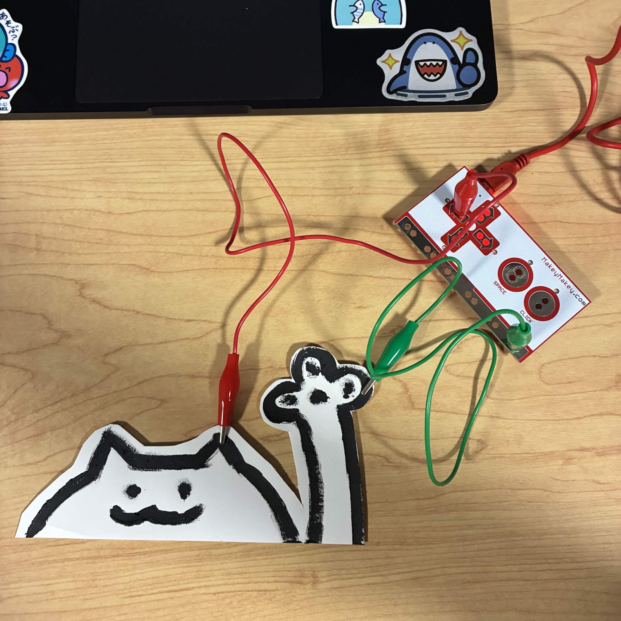
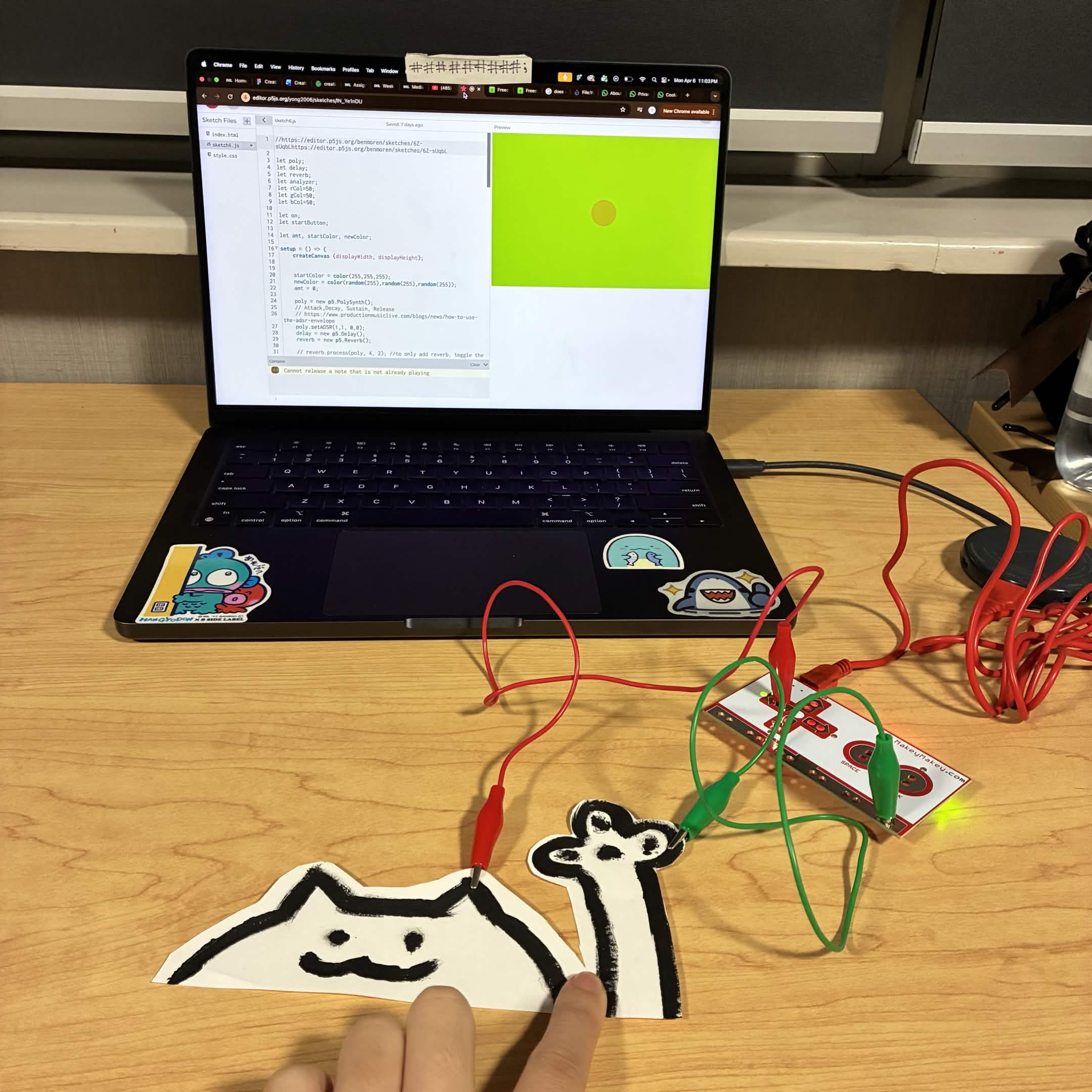
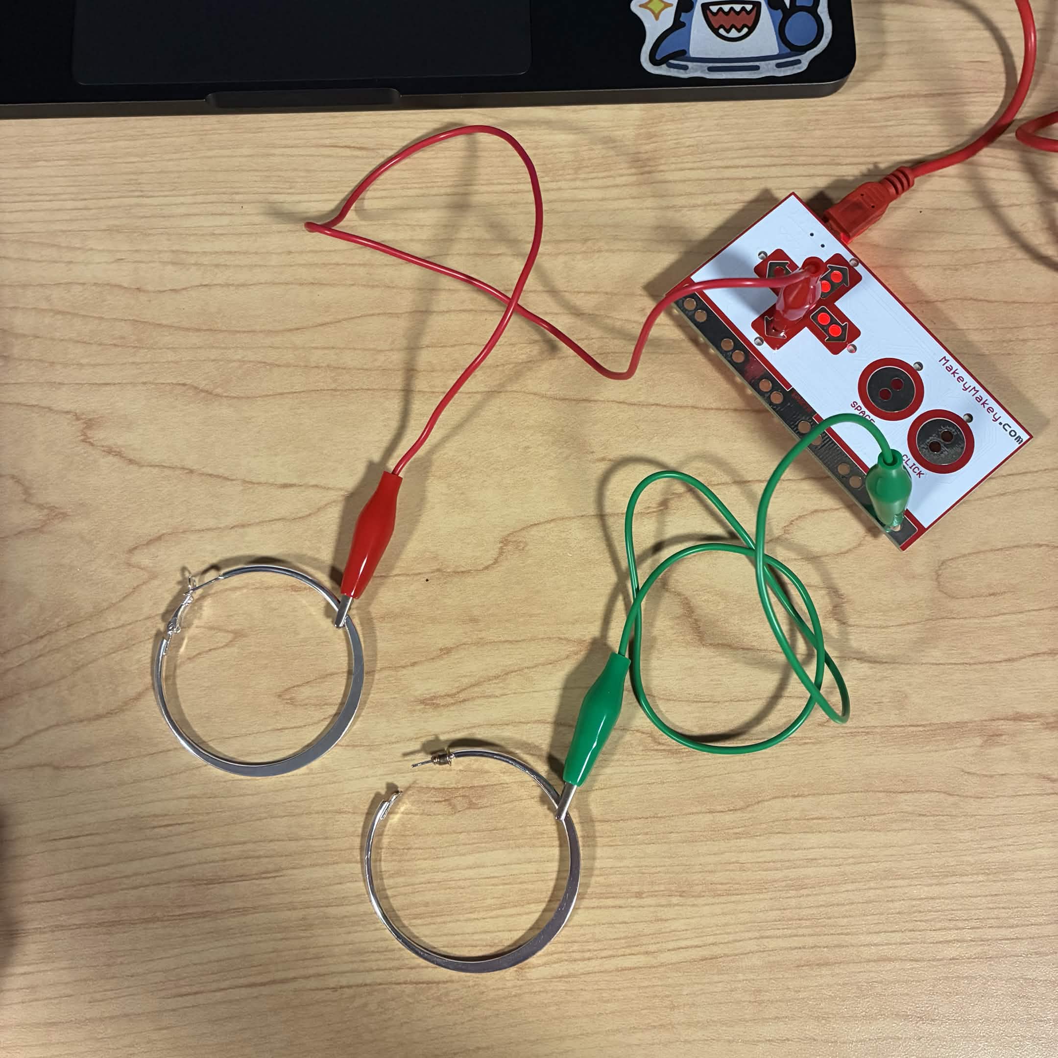
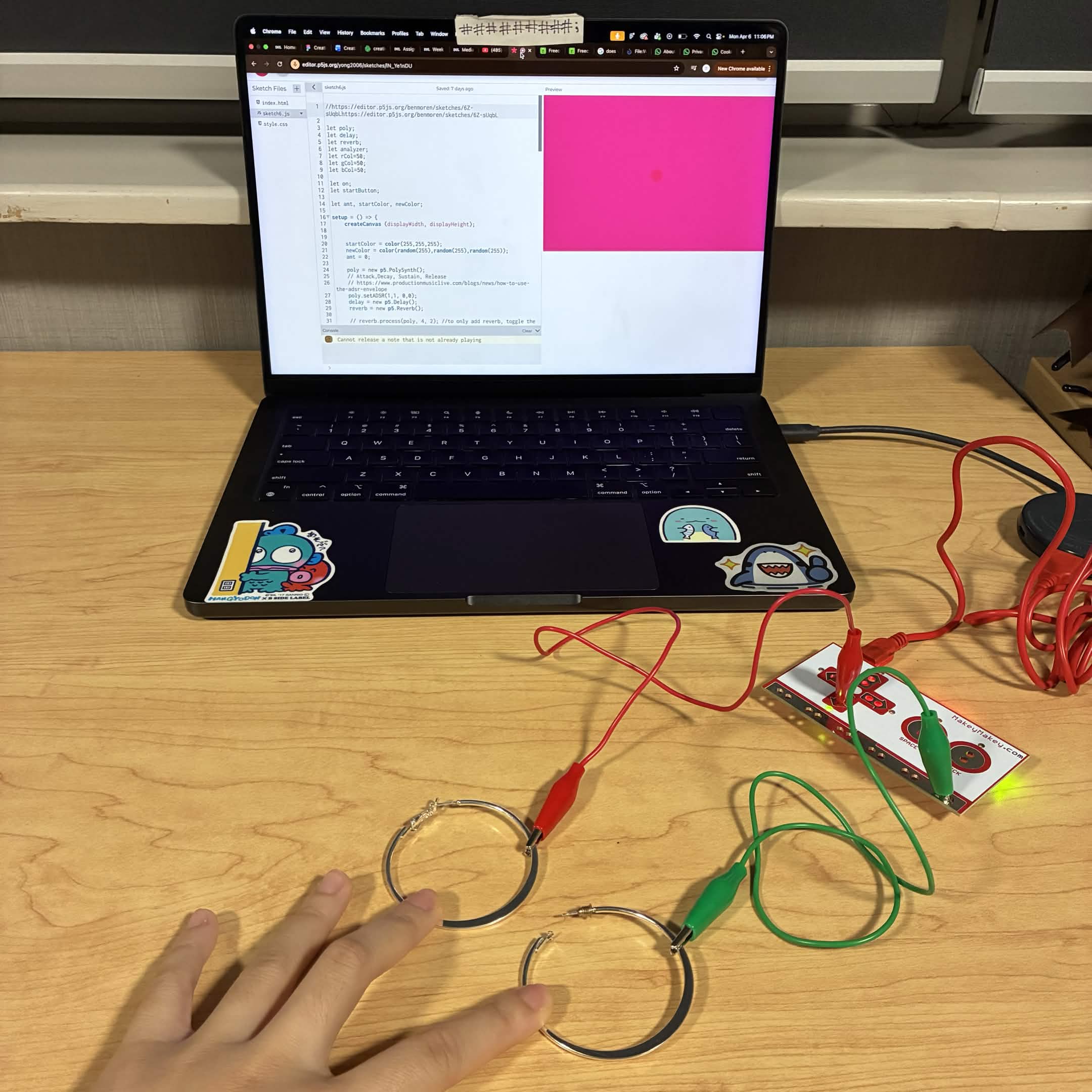
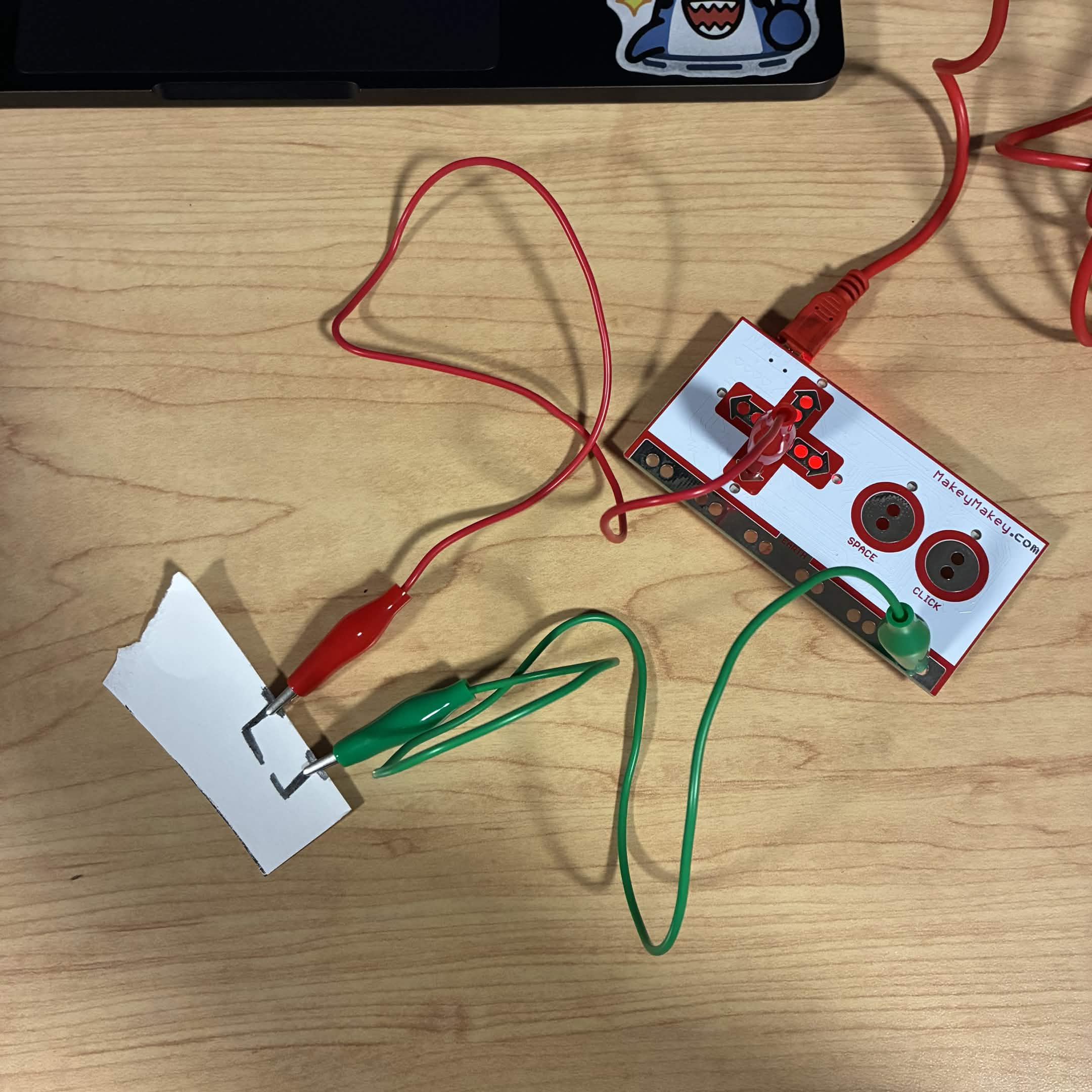
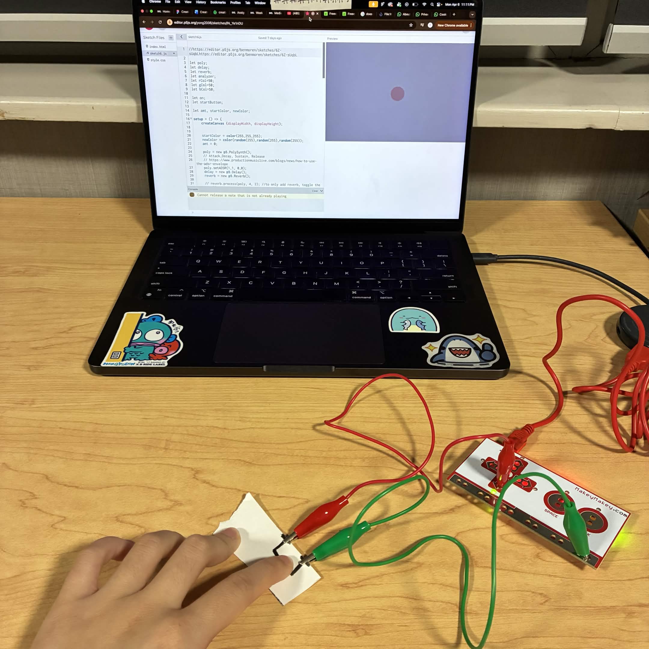
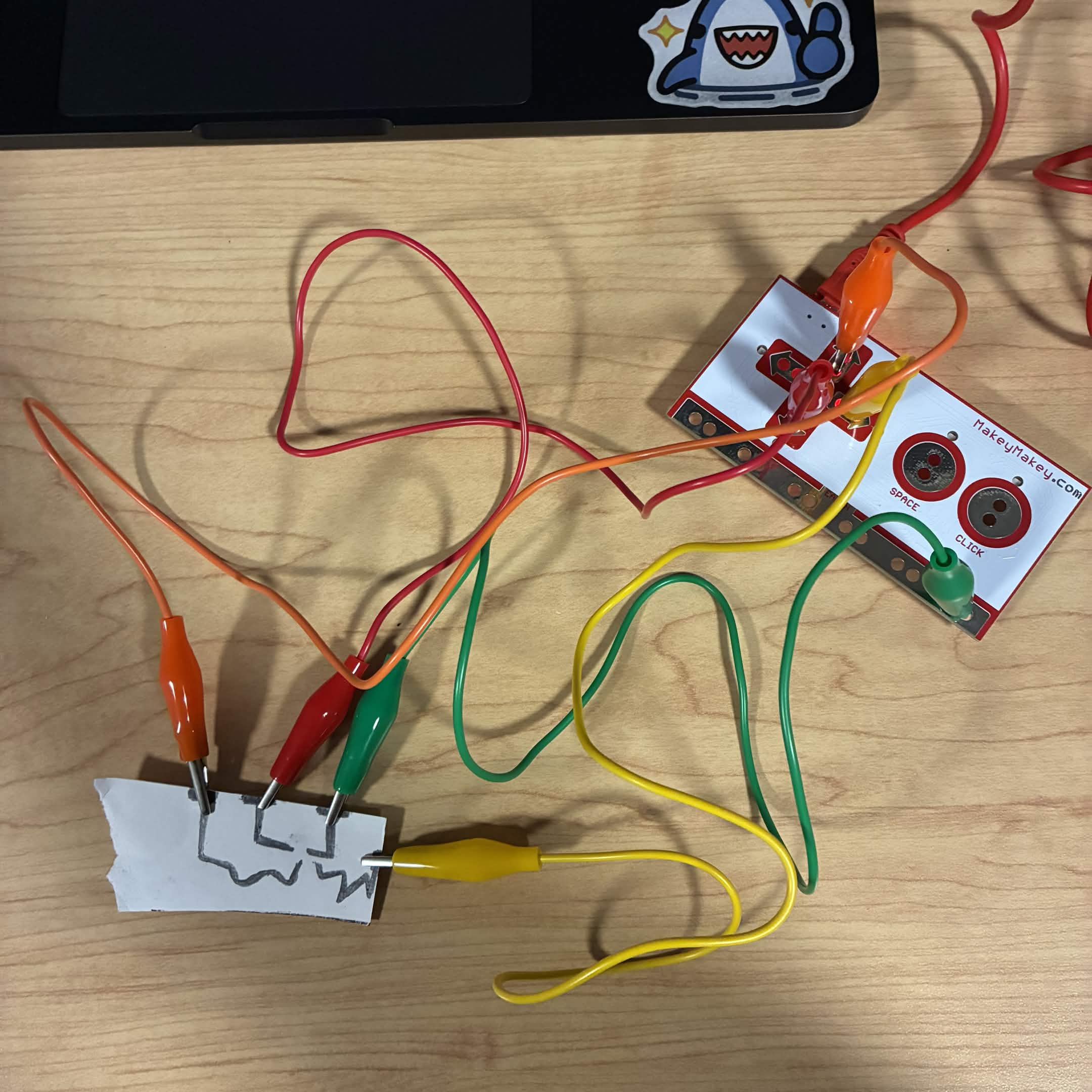
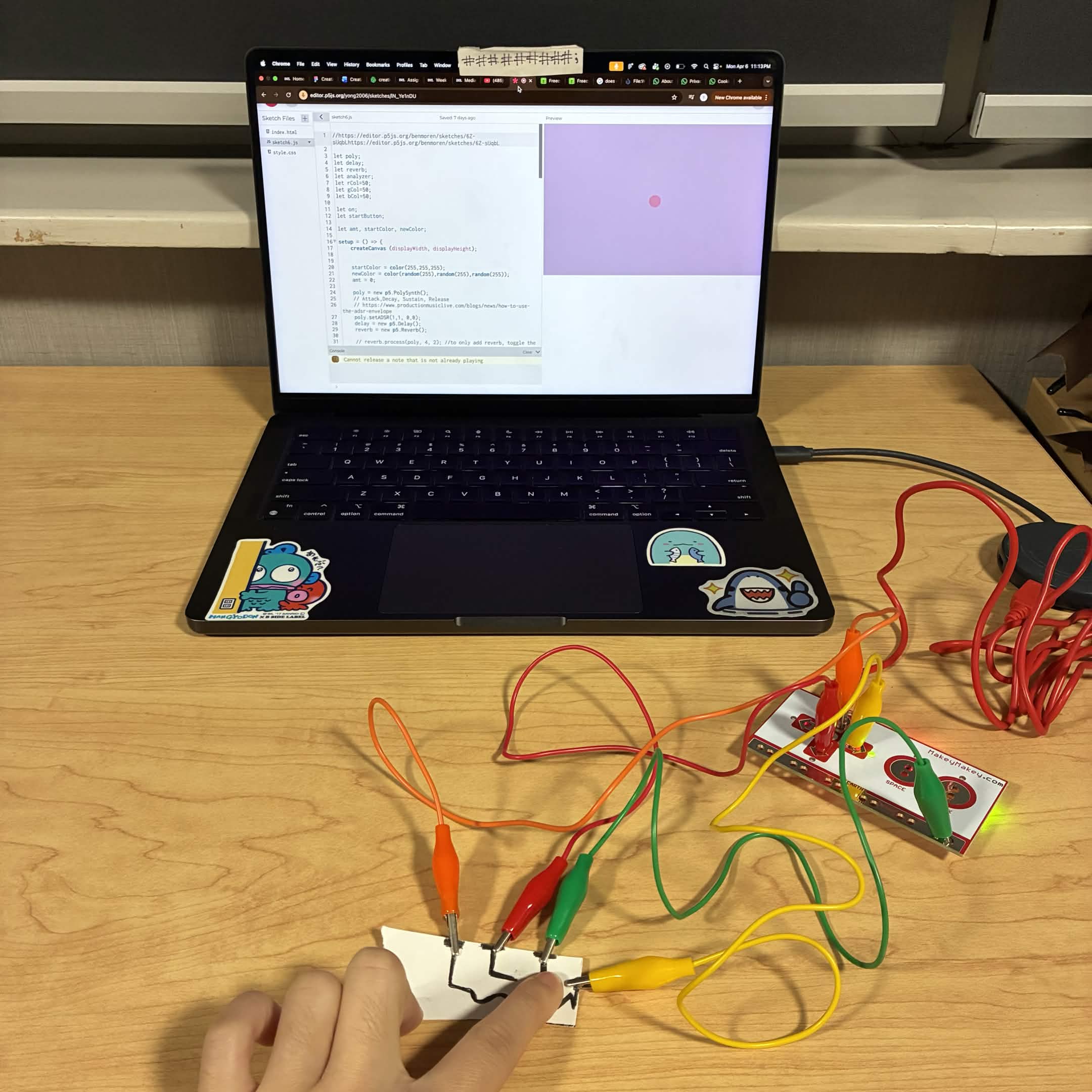
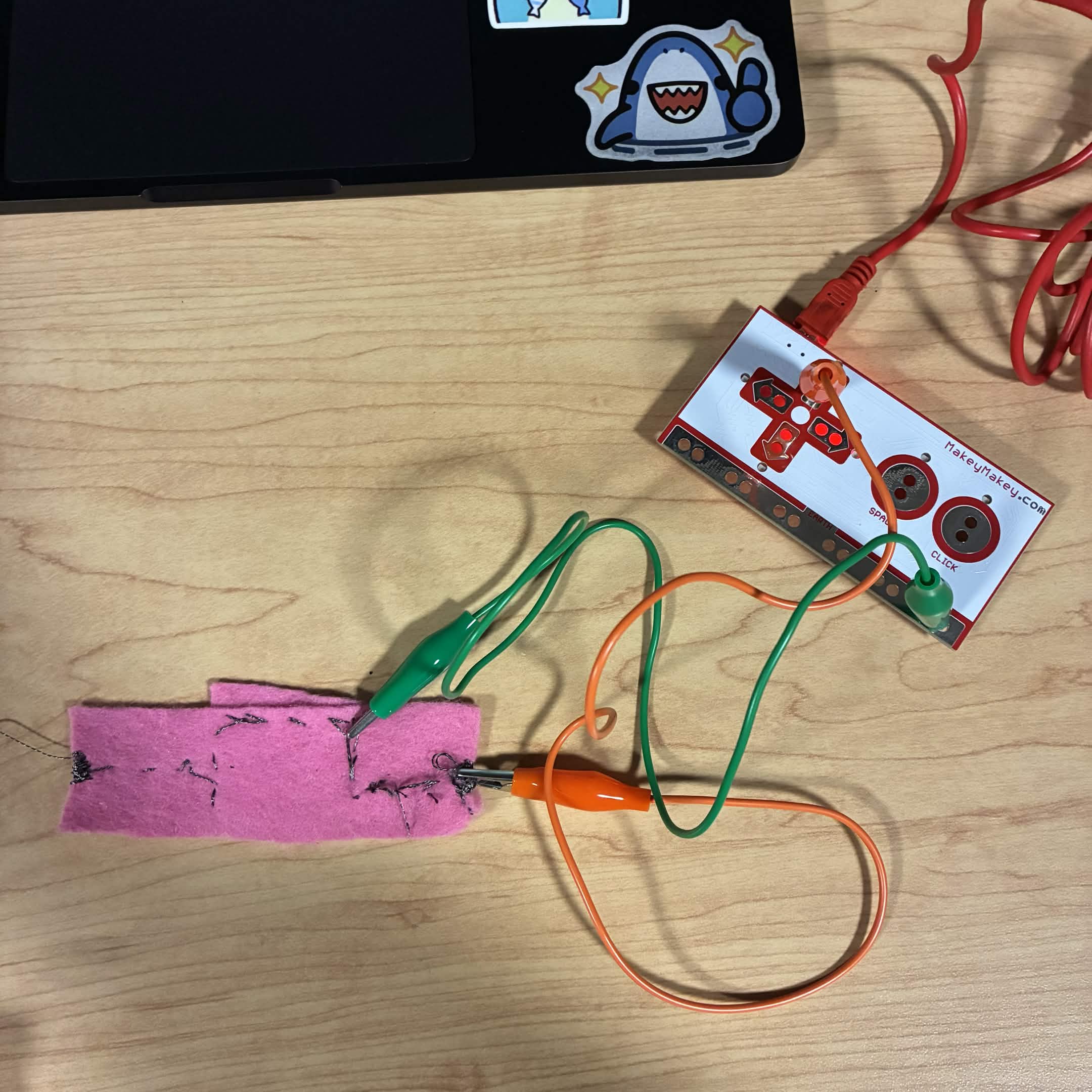
My exploration for activity 1 and 2 that helped developed my final project
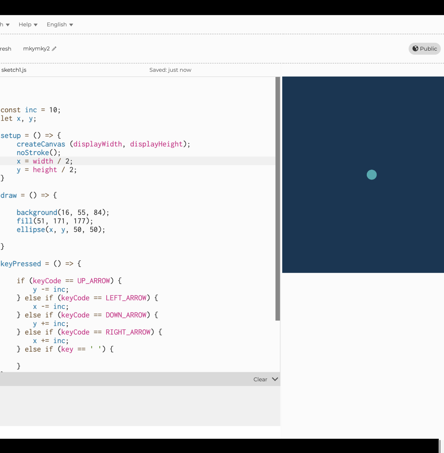
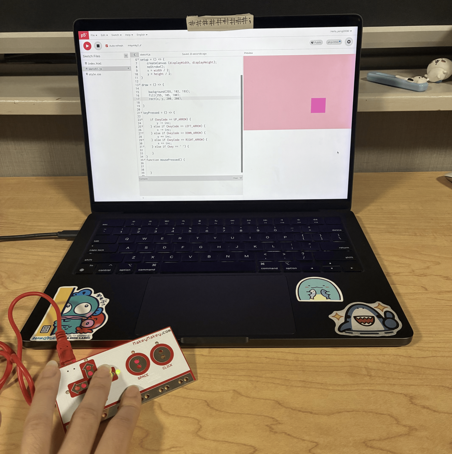
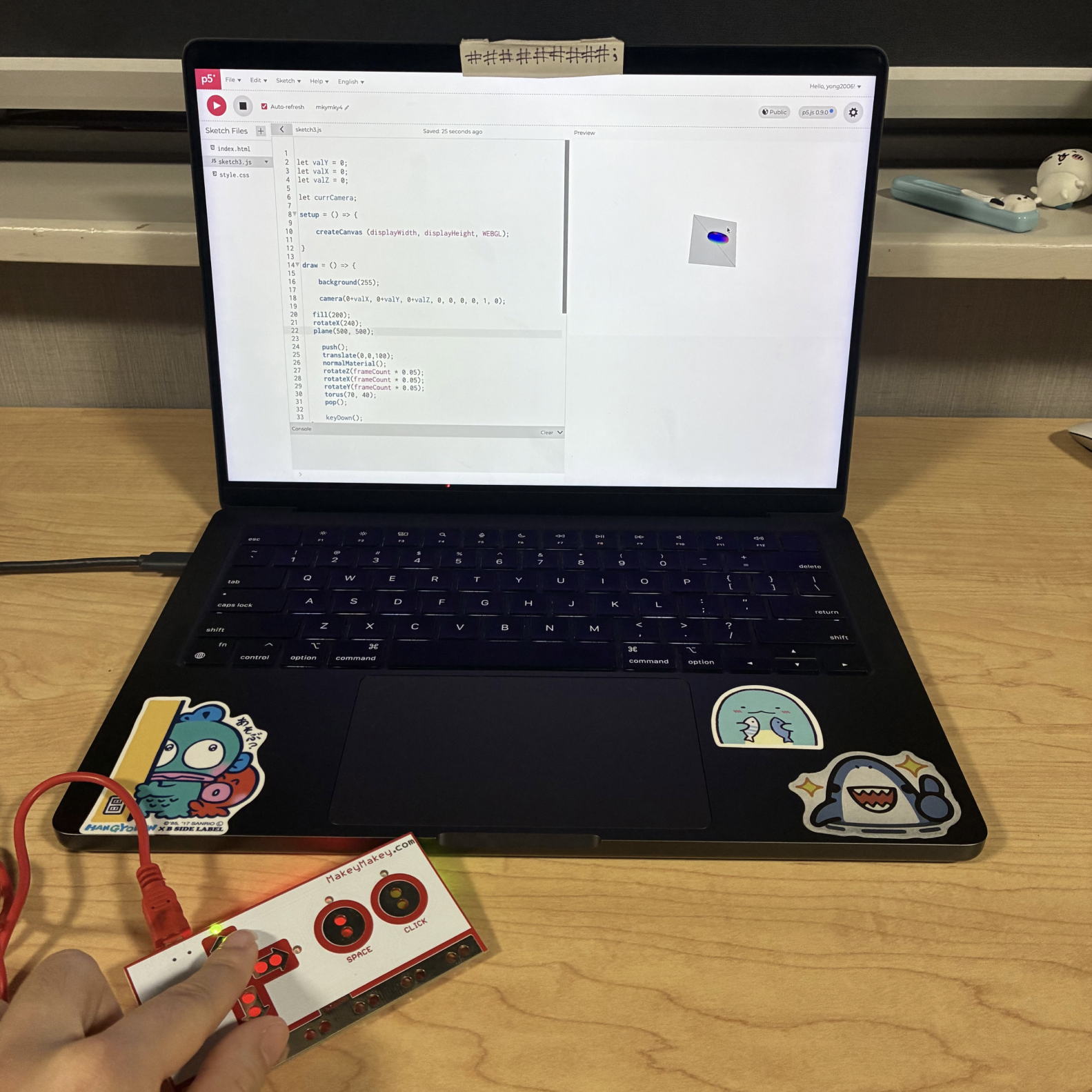
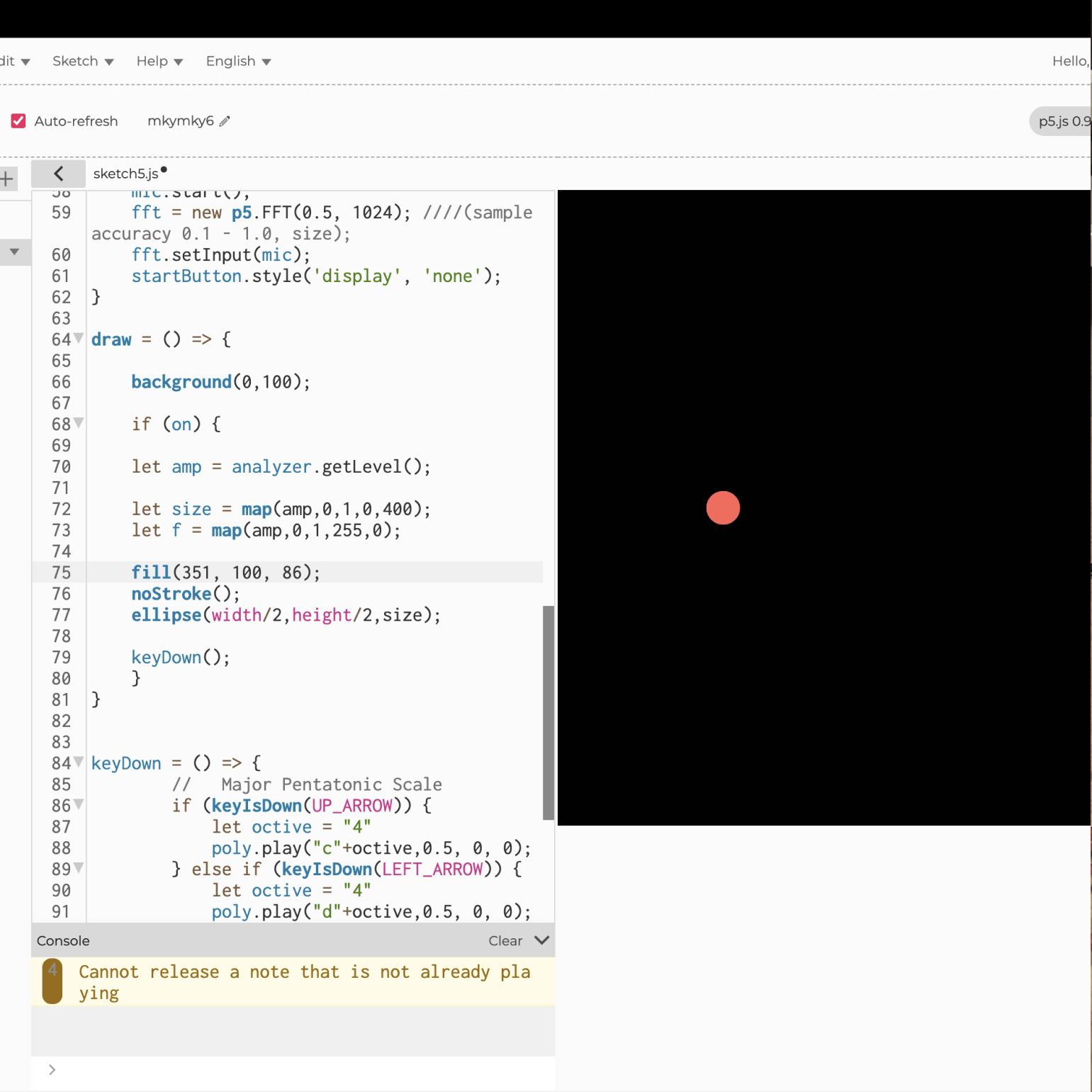
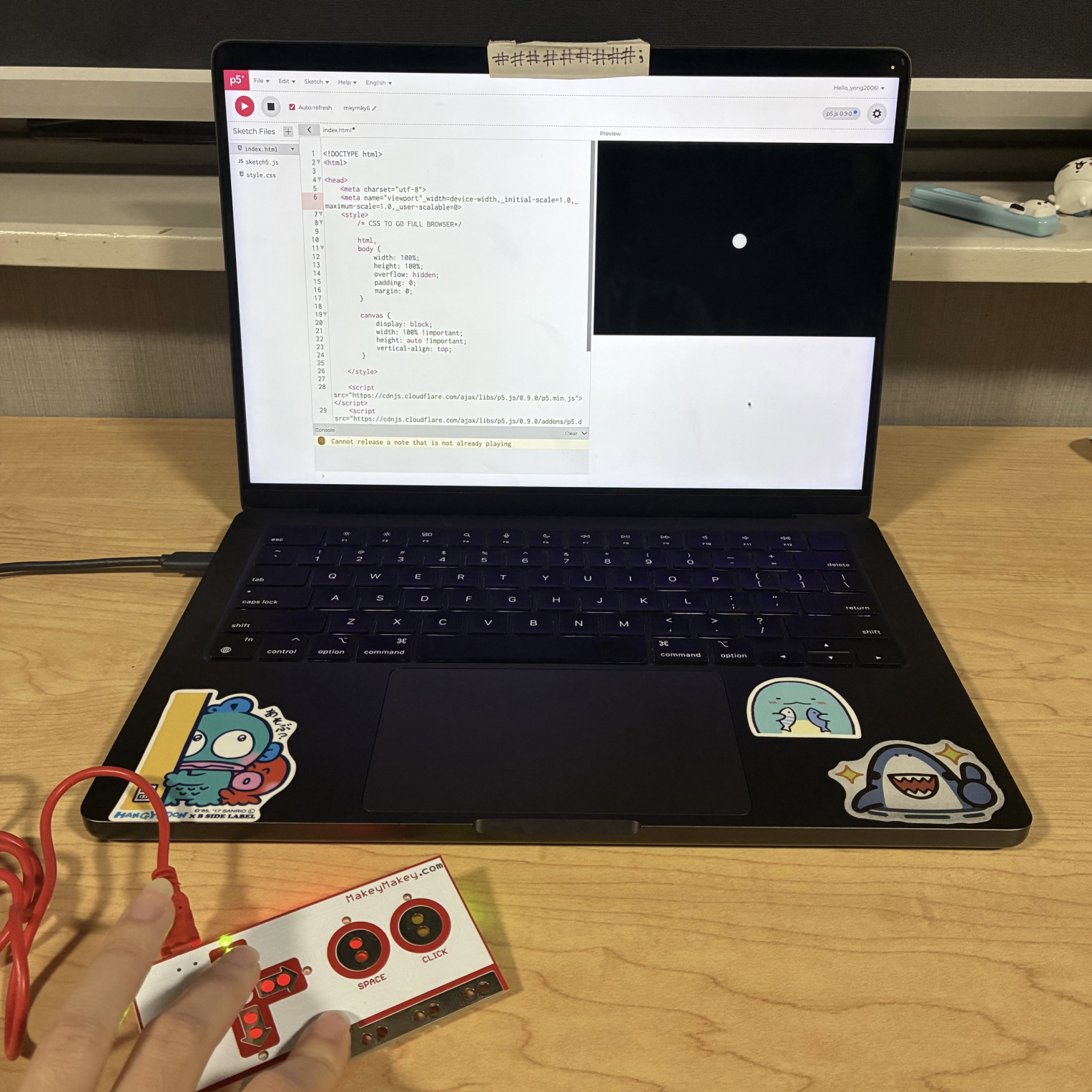
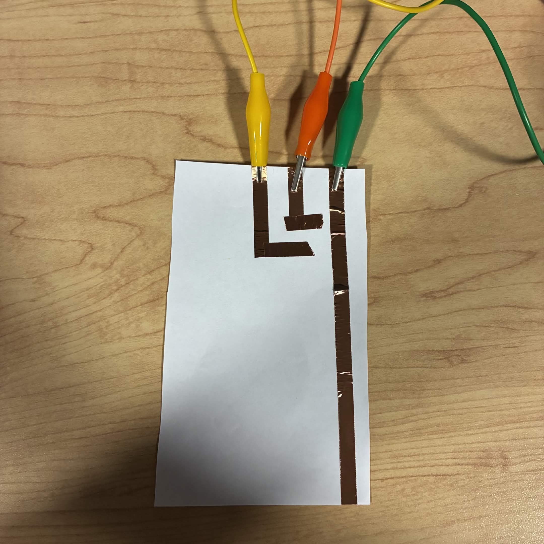
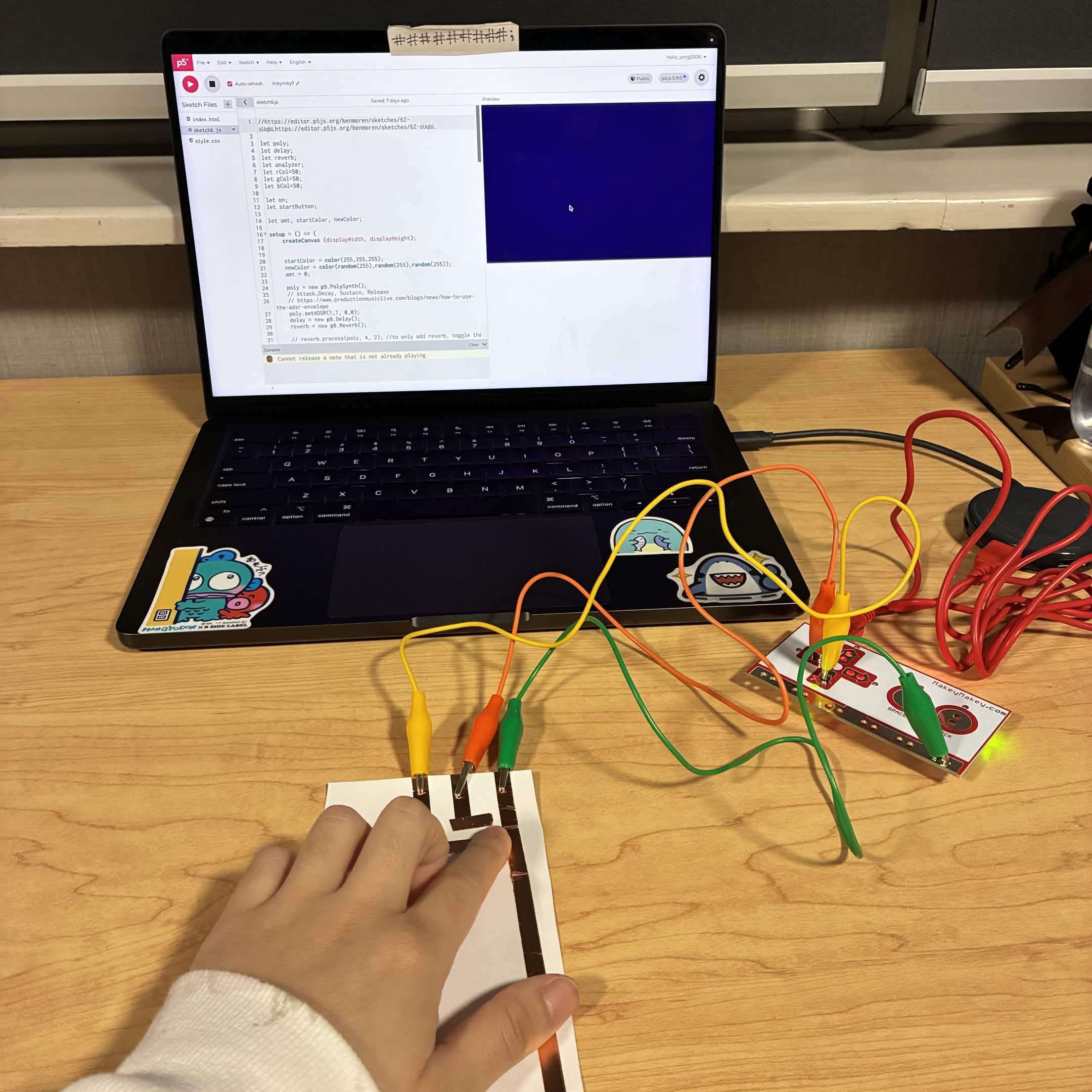
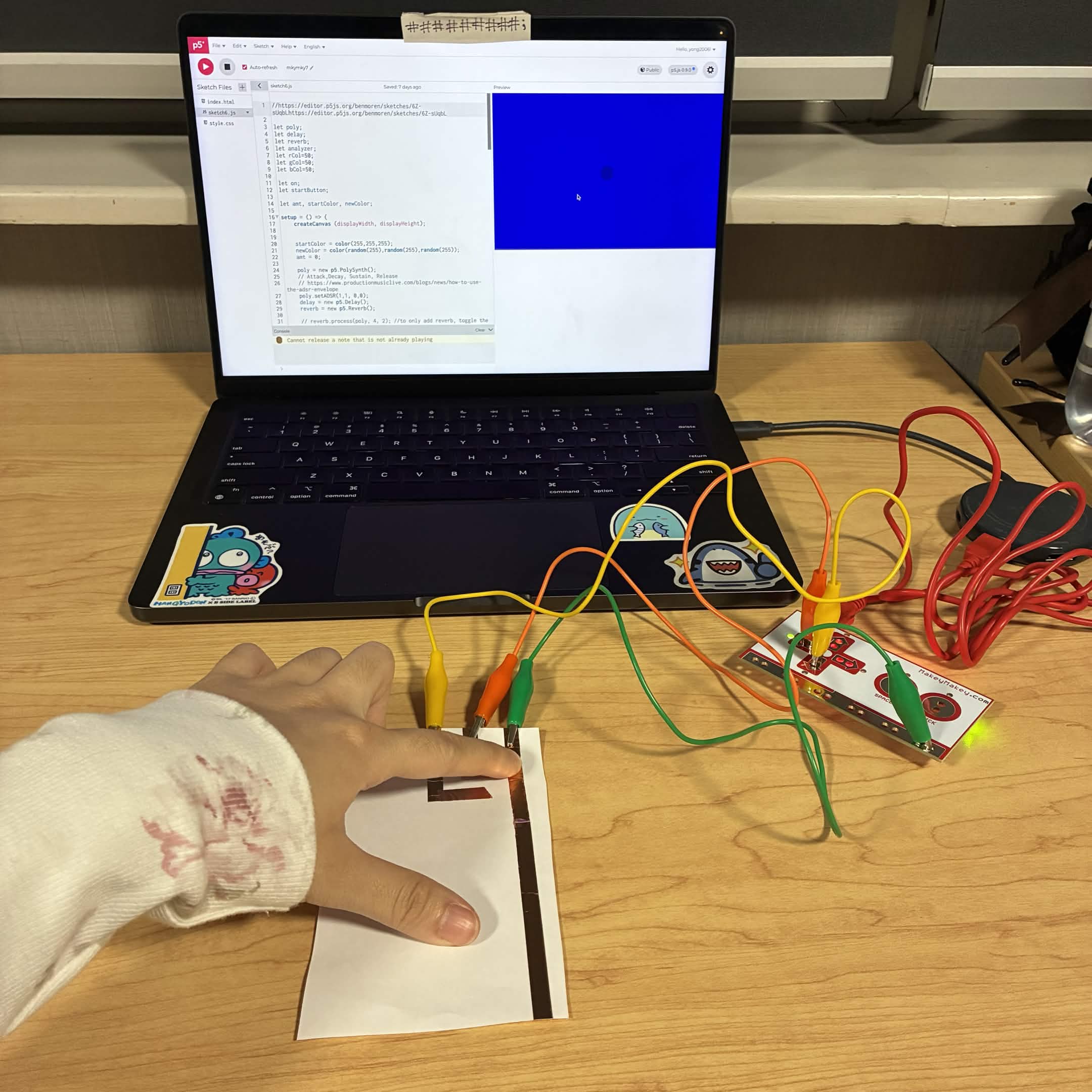
Activity 1
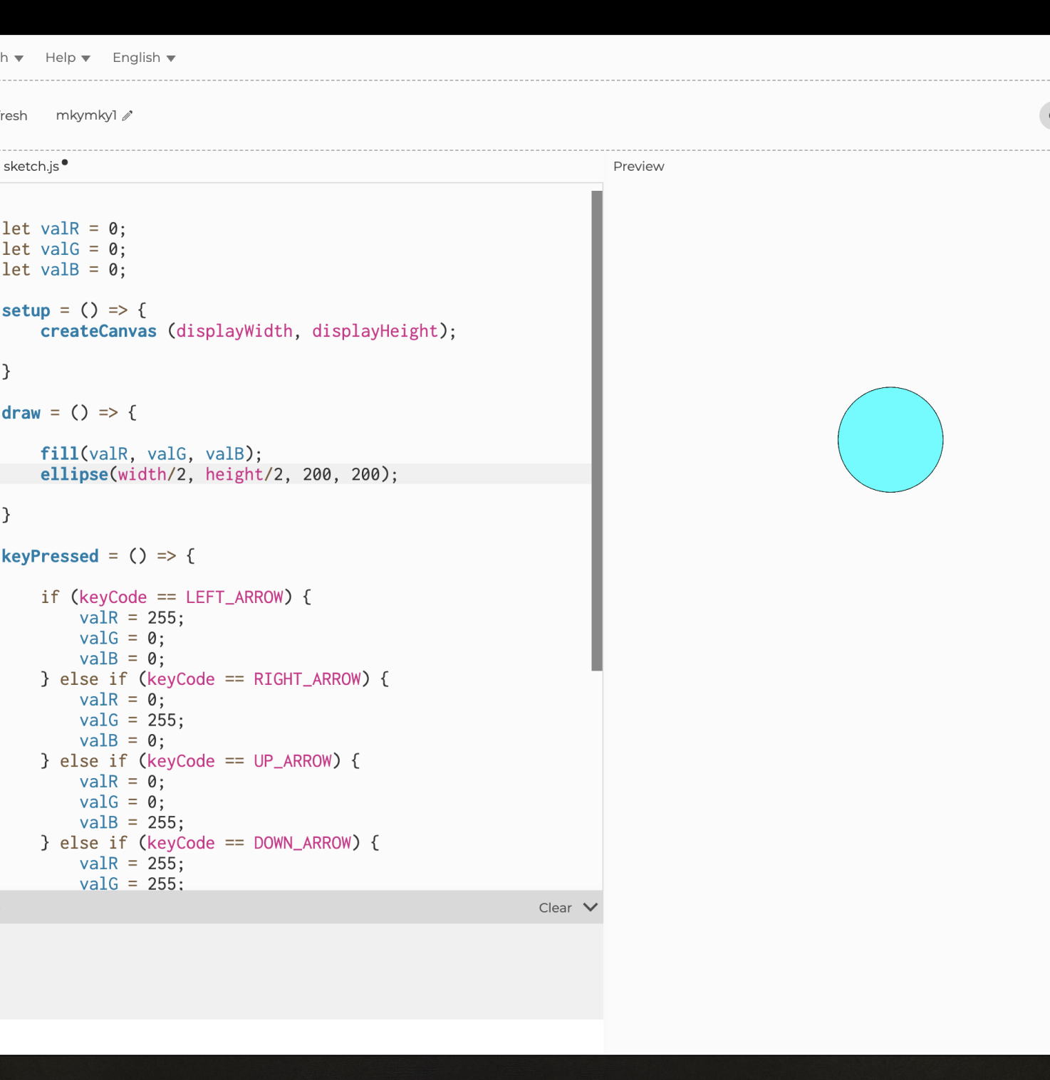
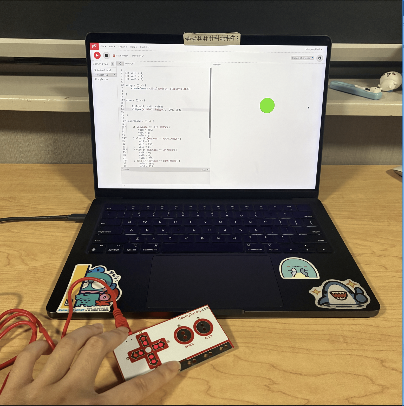
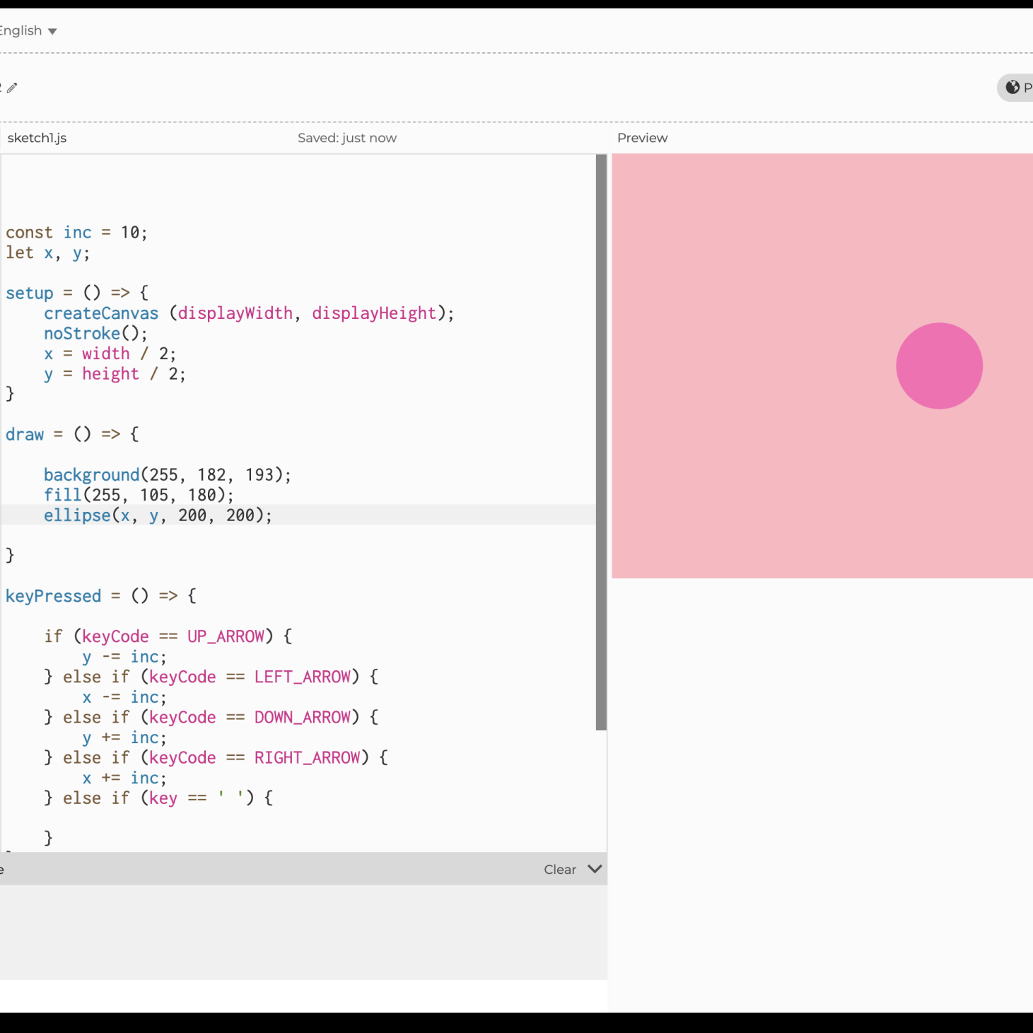
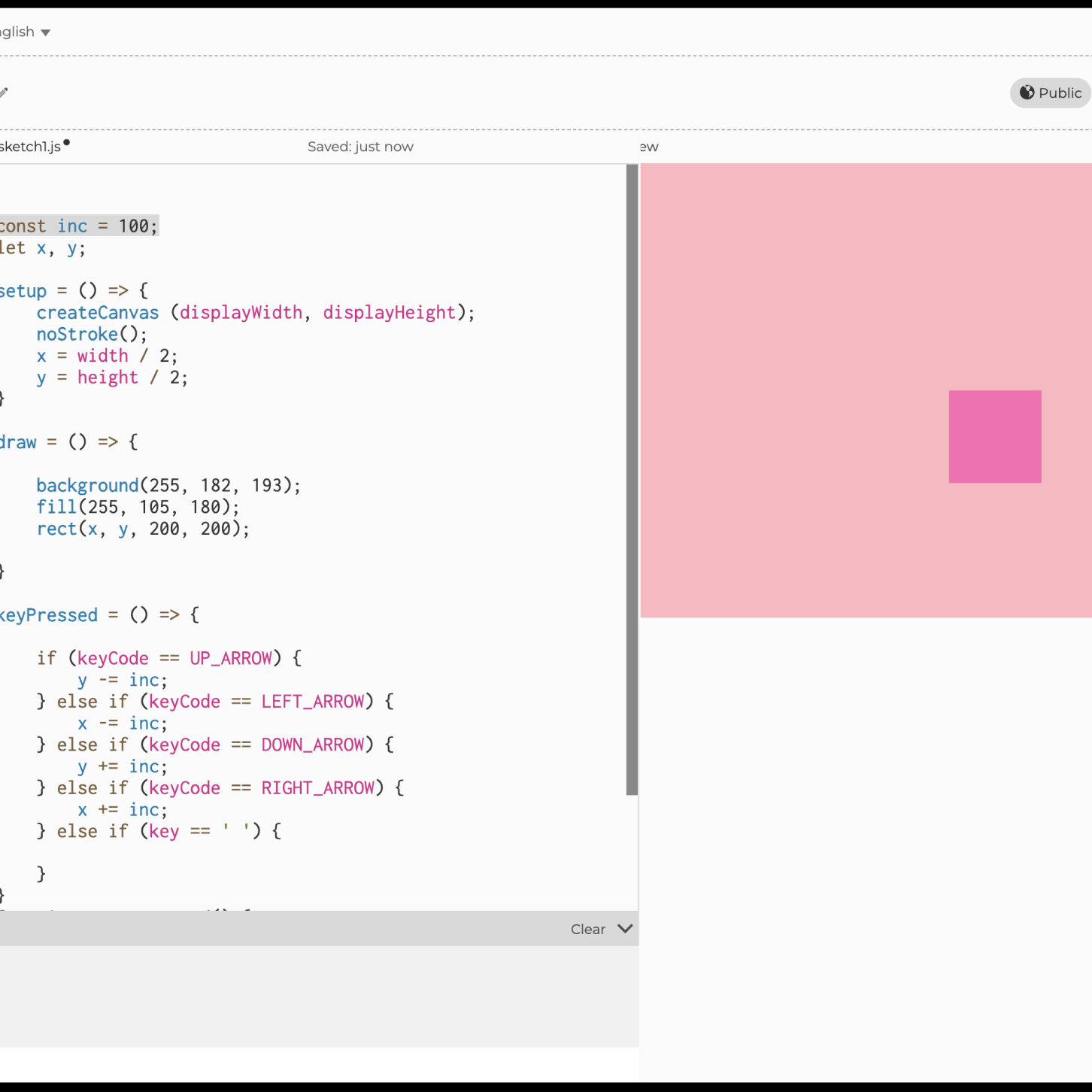
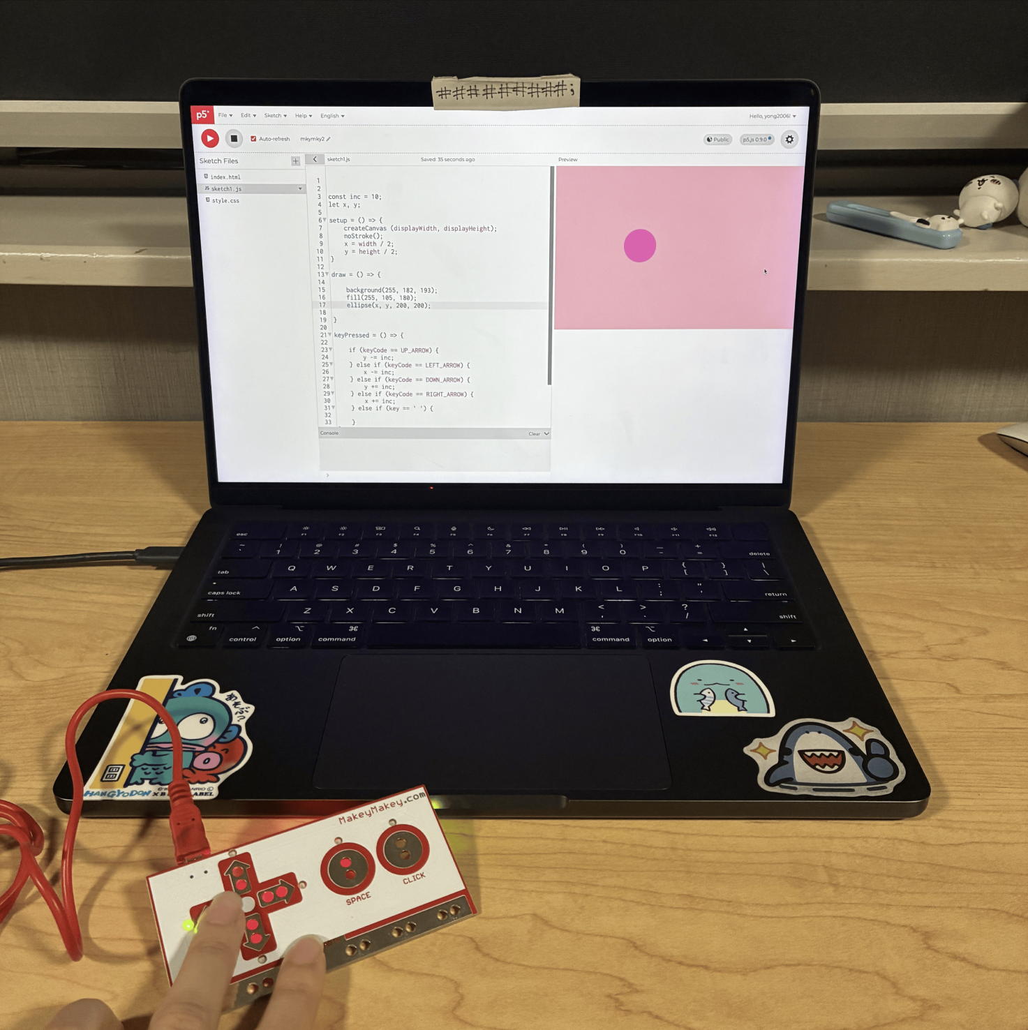
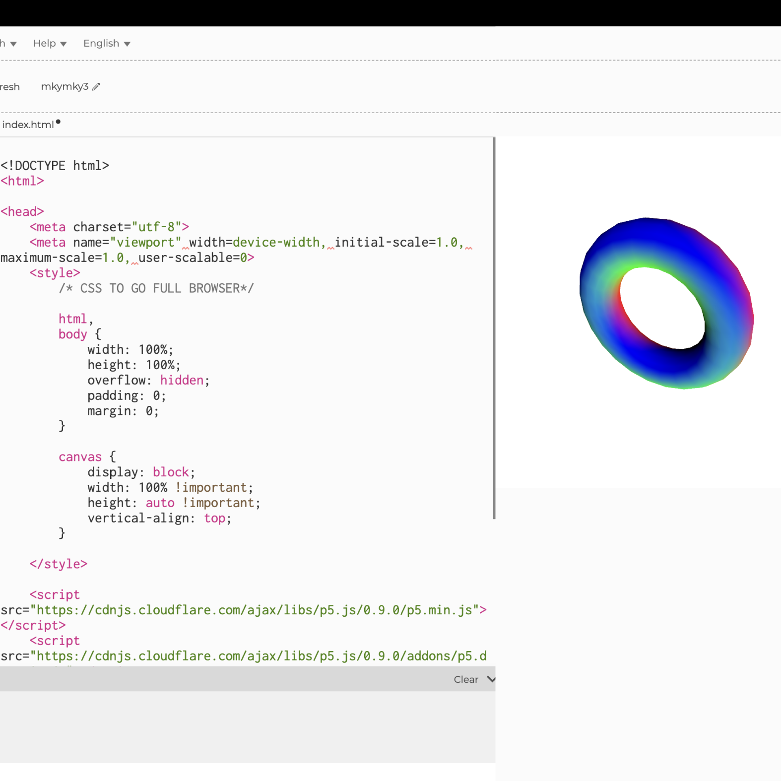
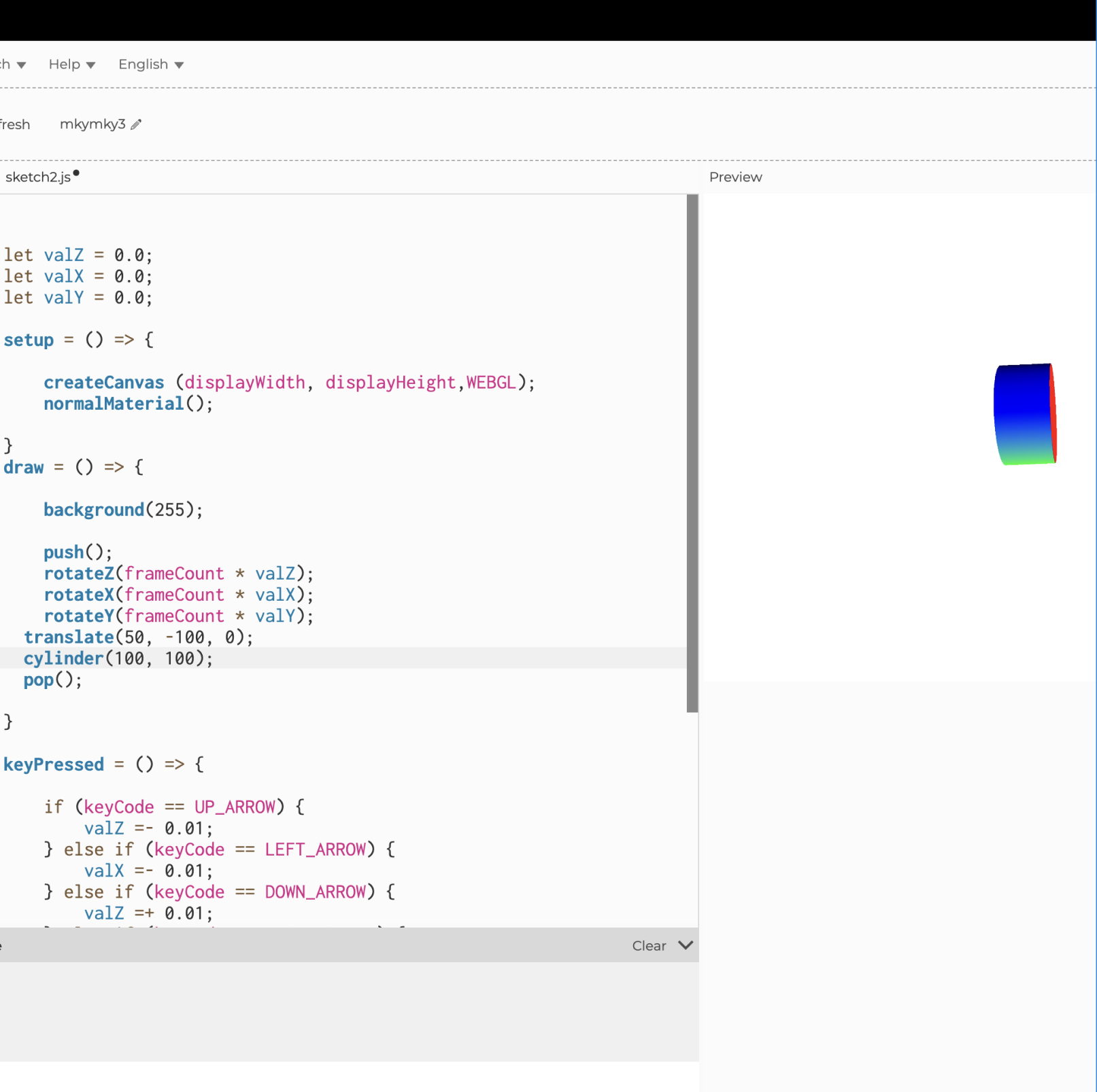
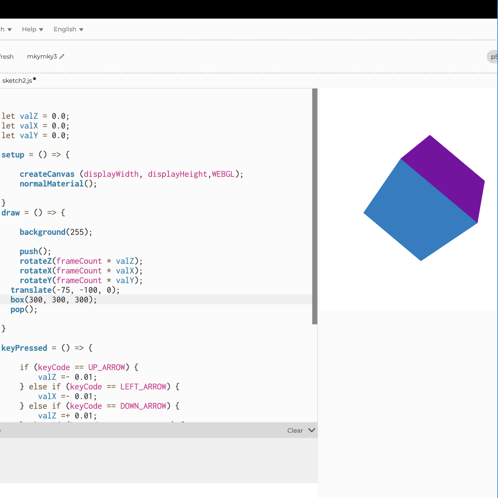

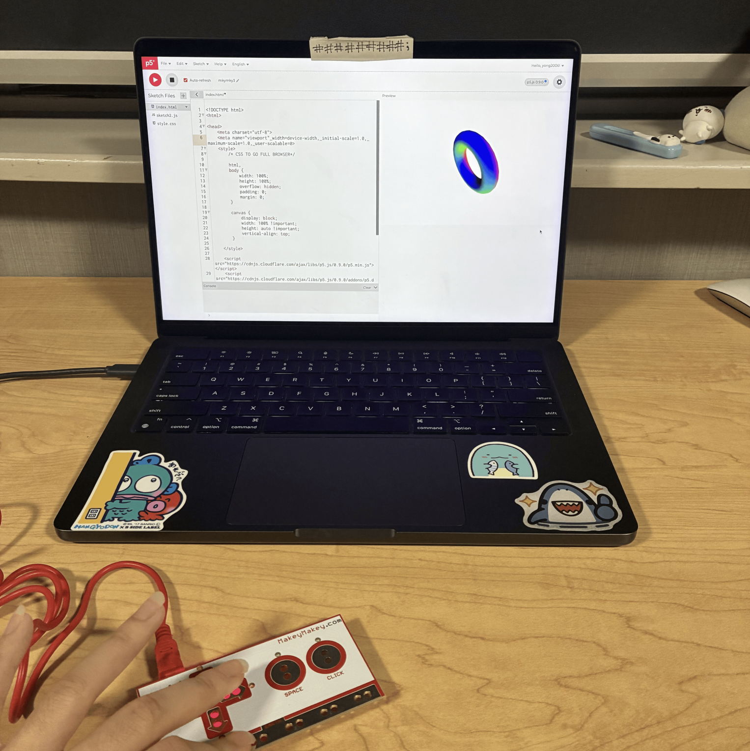
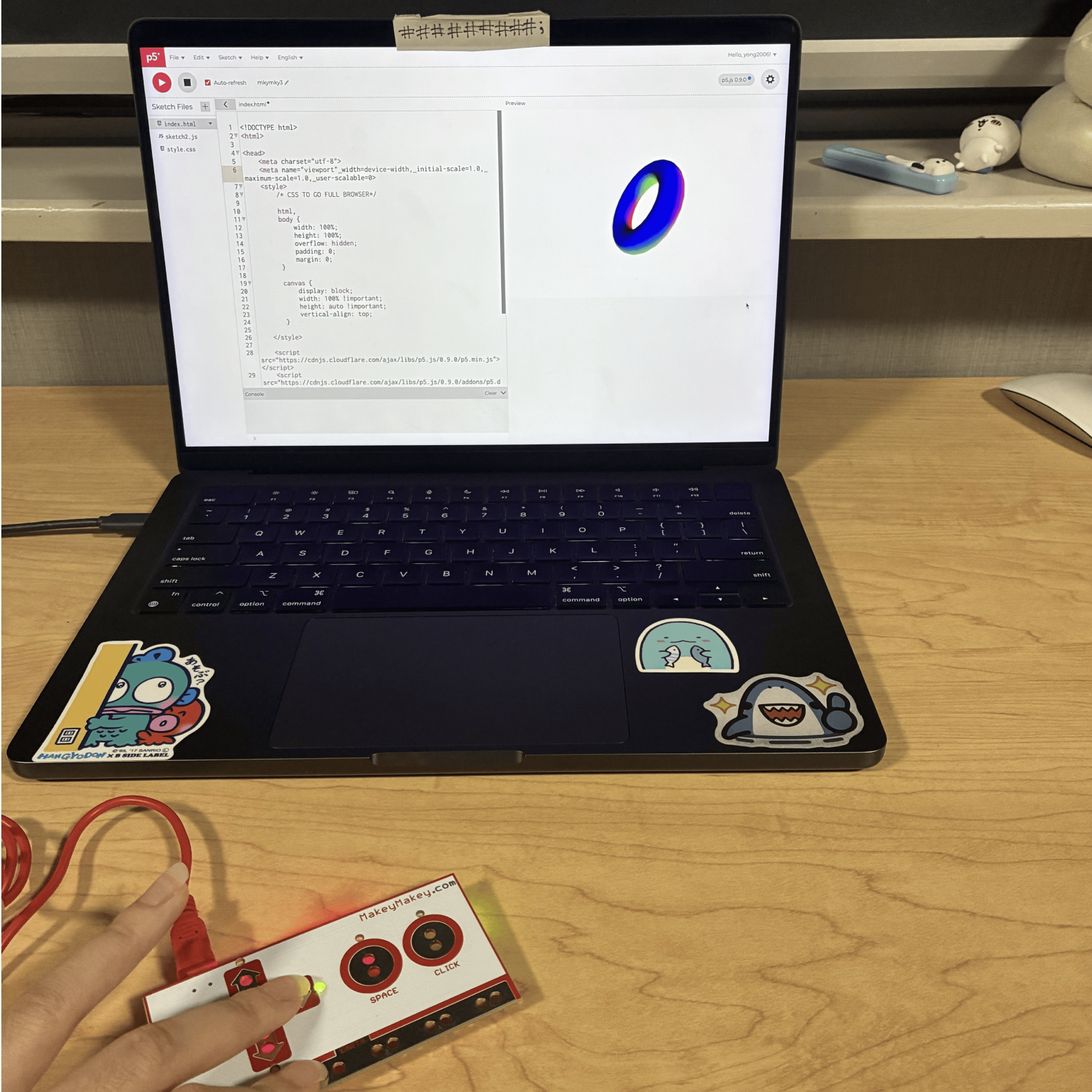
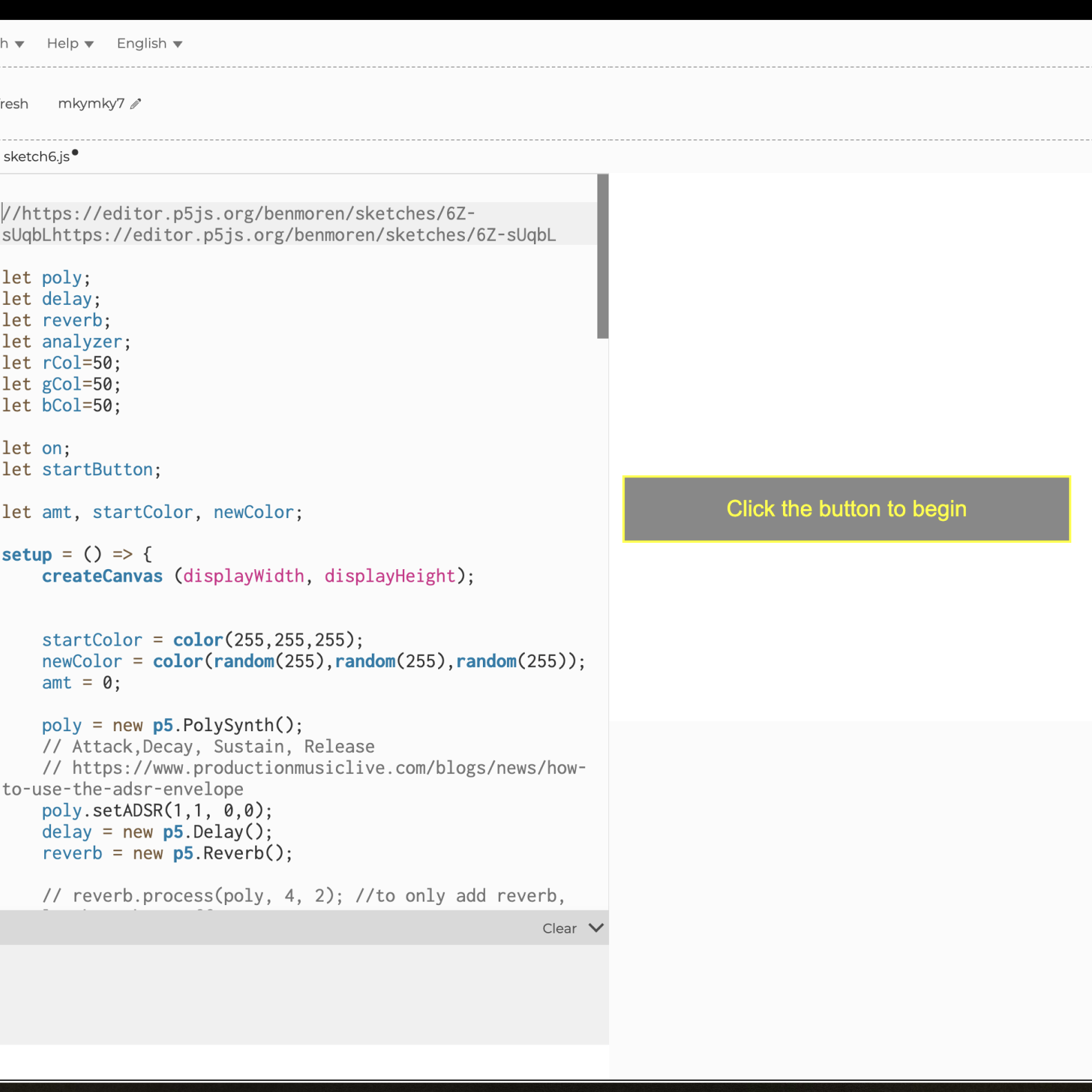
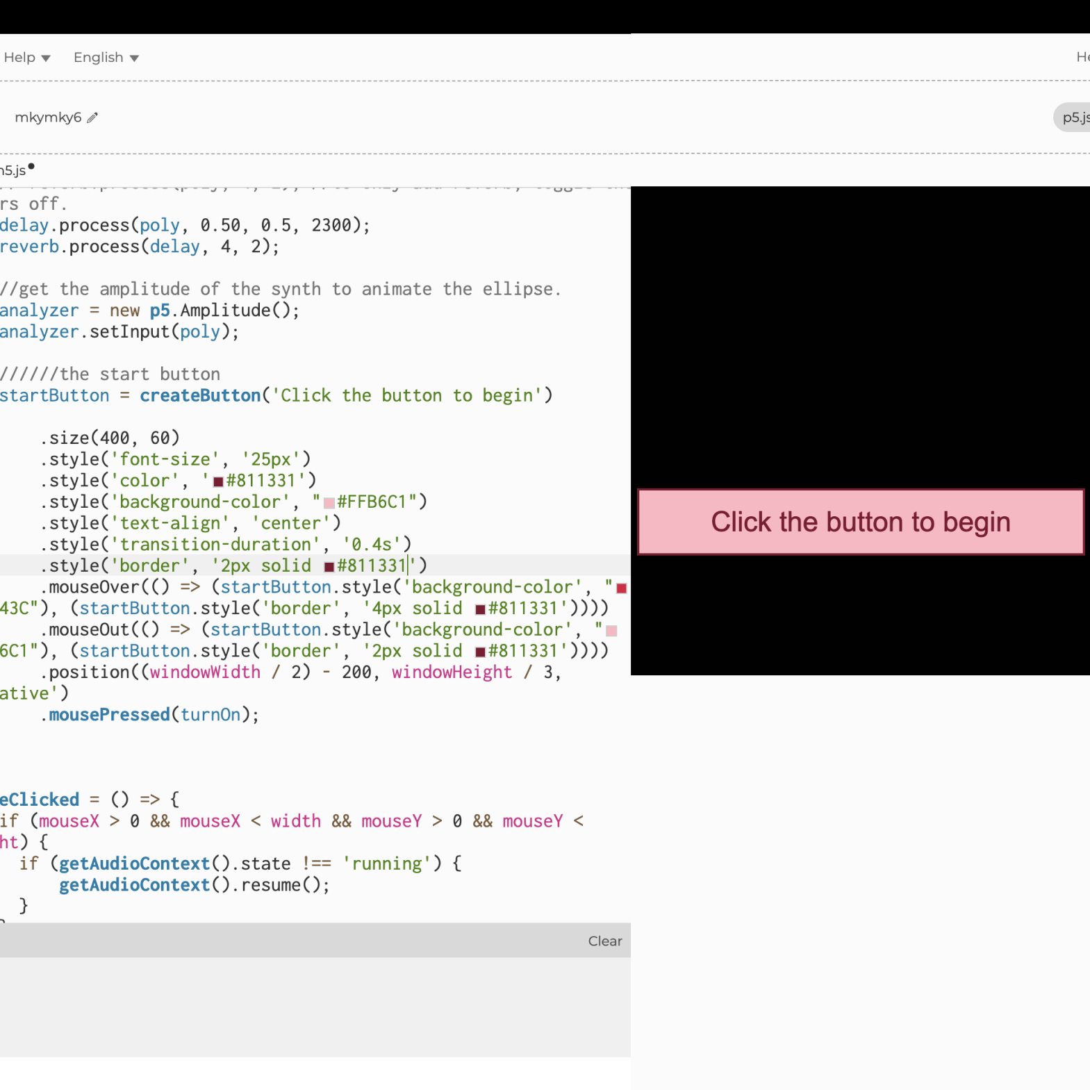
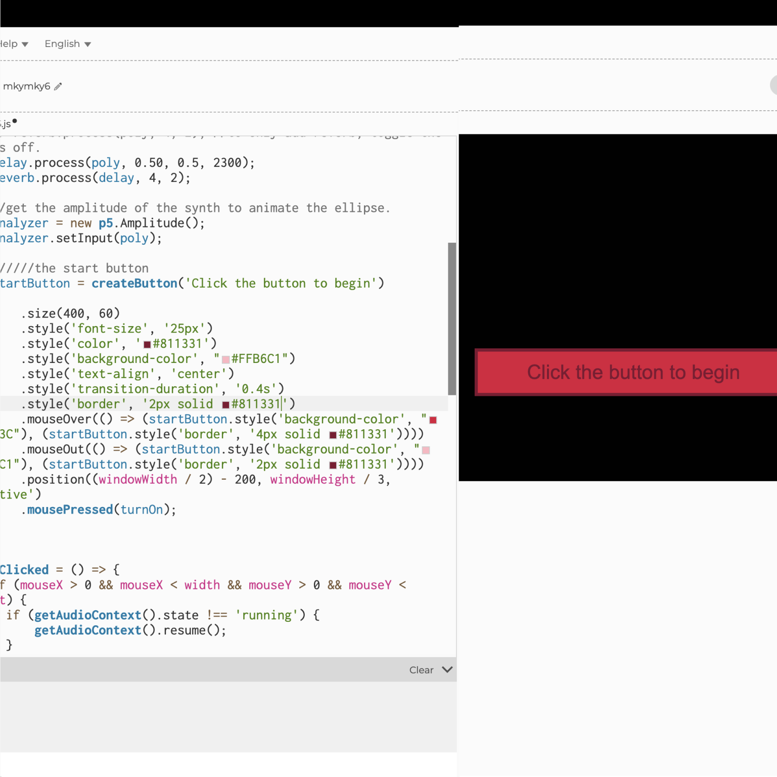
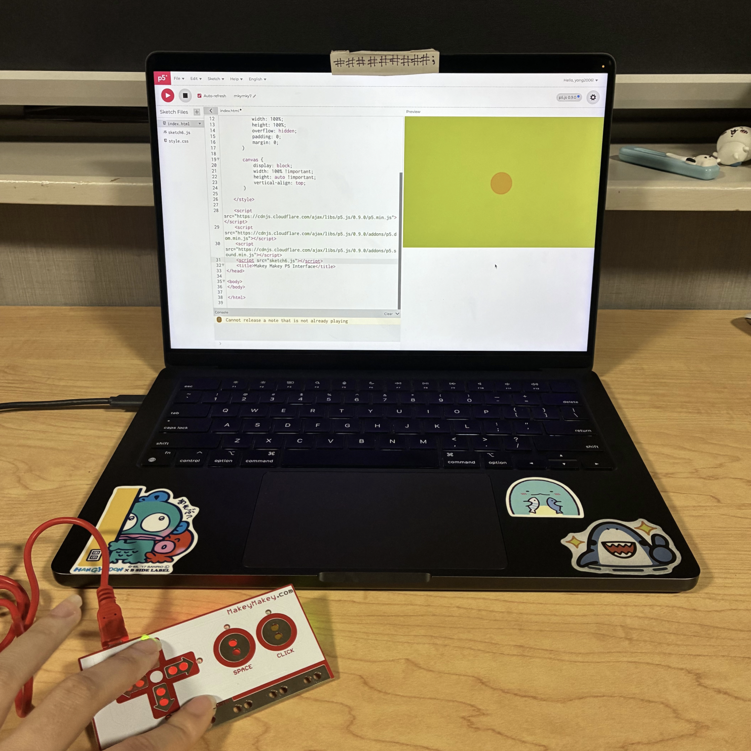
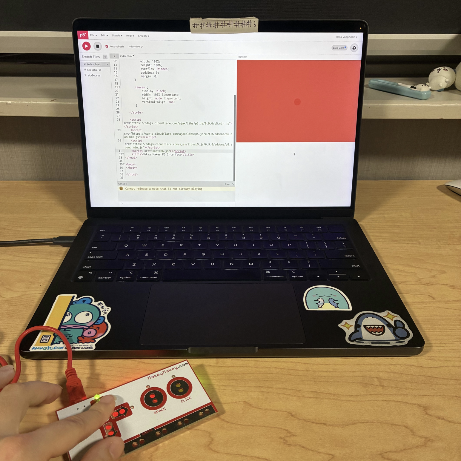
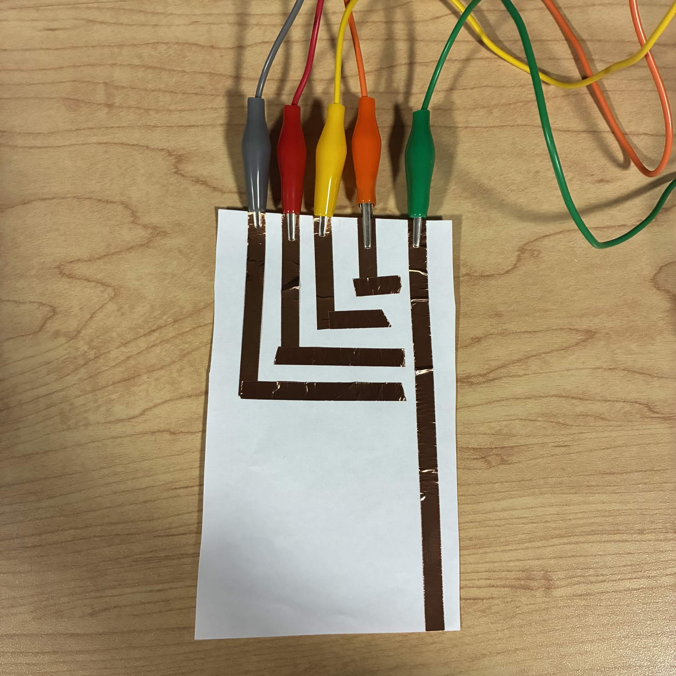
Activity 2
Project 3
Final Project 3 Design
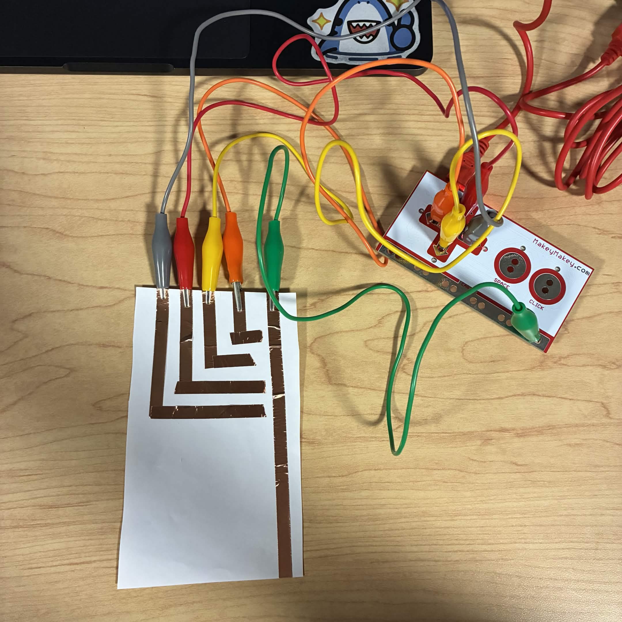
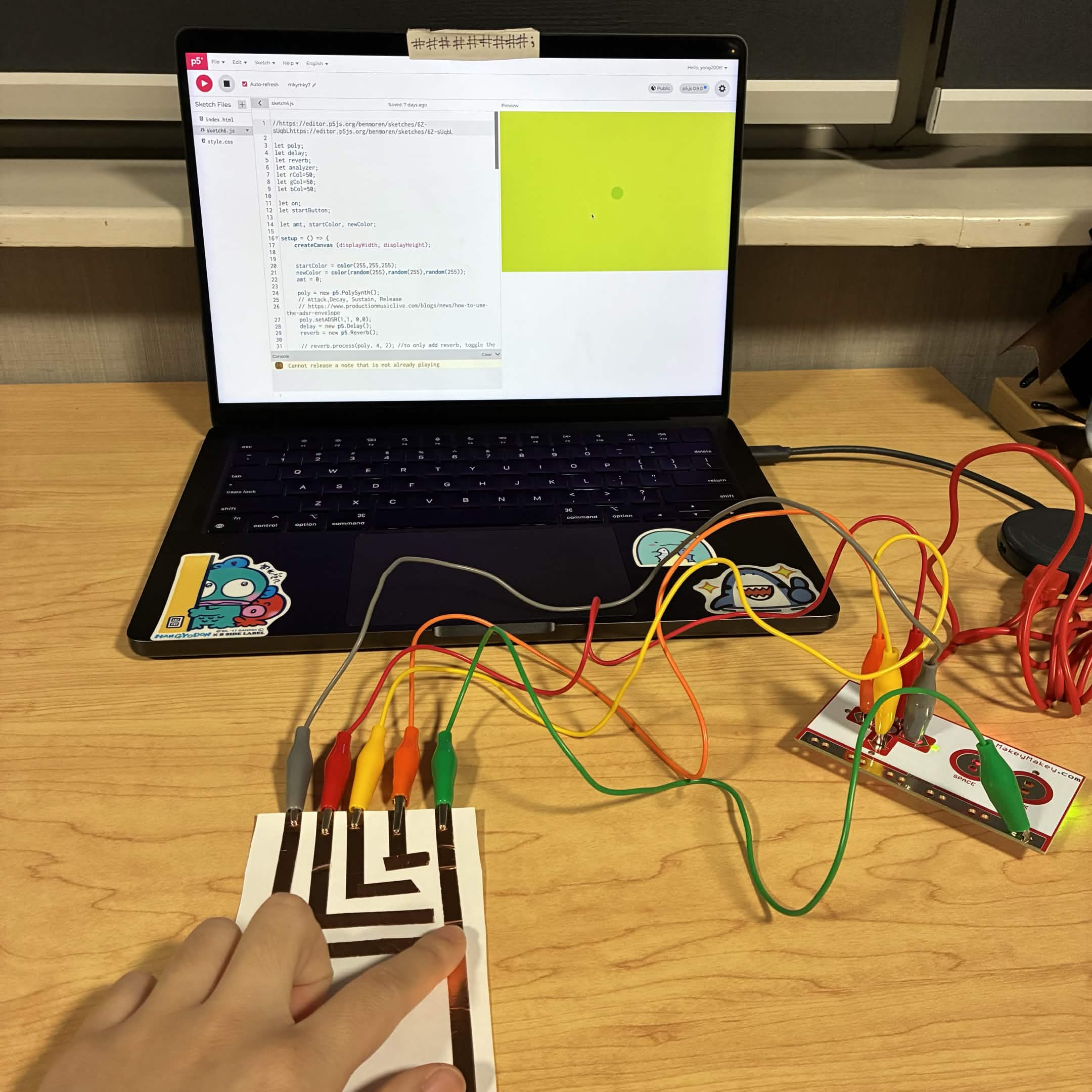
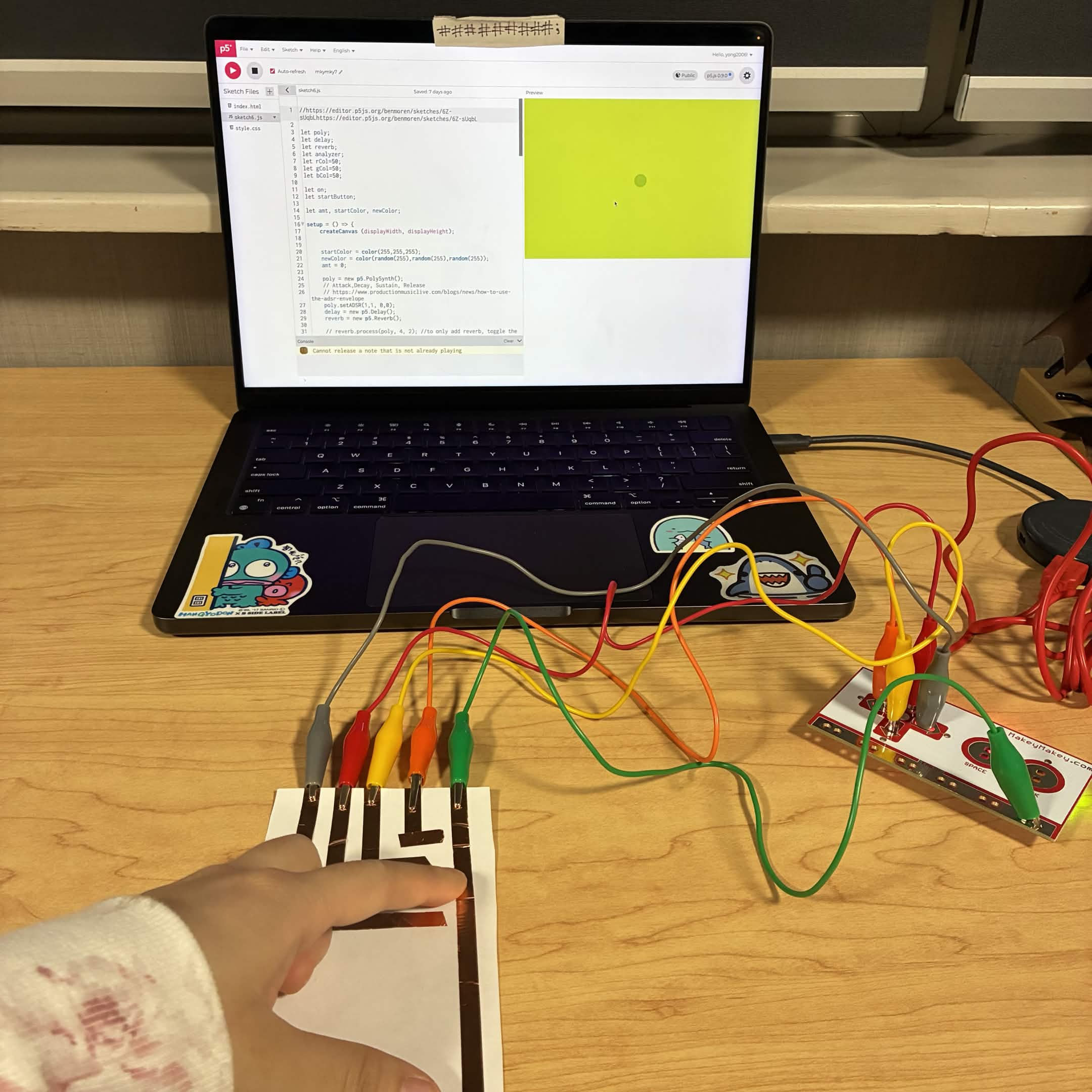
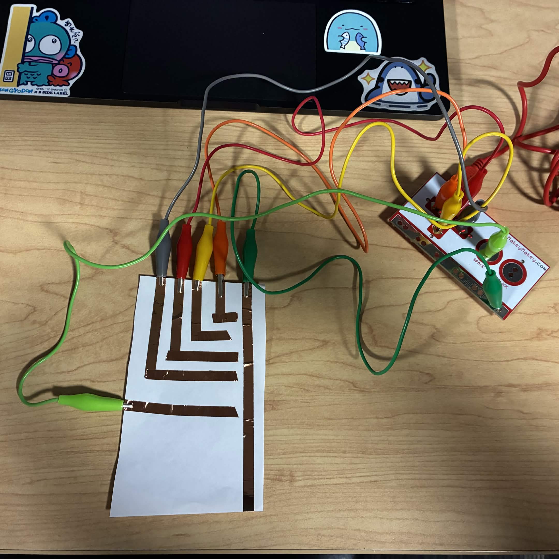
I designed an educational artifact that teaches people about different types of human teeth and tips for brushing one’s teeth. Users can take a toothbrush and press it against specific teeth on the model to learn about what that tooth is called and brushing tips to ensure proper dental hygiene. I used voice synthesis as well so the information can be relayed through visuals or auditory interaction.
Powered by w3.css